


Ziroli SBD-3 Dauntless build
 09-10-2017, 02:04 PM
#1

Thread Starter
Join Date: Sep 2014
Location: Scottsdale, AZ
Posts: 169
Likes: 0
Received 0 Likes
on
0 Posts
This will be a Ziroli 100" SBD-3. I have the following parts that I plan to use:
Zenoah GT-80
Robart electric retracts
dBalsa cockpit kit
PCK full kit
I have researched Neo, Sam, Spitzed, Wallace, Wayne and Frank's build thread for countless hours. I have recorded so many notes that I went back to the Ziroli notes, and re-did the whole thing so I don't forget steps. I even included pictures. It grew from 7 to 48 pages.
I have 3 books I purchased for scale details. This being my first build off of plans, I want to make this as scale as possible. But... since I spend half of the year or more away from my shop, the build process will not be super fast.
 09-11-2017, 08:49 AM
#2
Thread Starter
Join Date: Sep 2014
Location: Scottsdale, AZ
Posts: 169
Likes: 0
Received 0 Likes
on
0 Posts
A little more to add to the list. I plan to use the following mods:
Sam's Detachable firewall
Air flow through the vents
Hatches - some just for scale
Scale linkages that I saw from Wallace
Spitz's tailwheel
Sam's Detachable firewall
Air flow through the vents
Hatches - some just for scale
Scale linkages that I saw from Wallace
Spitz's tailwheel
09-11-2017, 02:11 PM
#5

My Feedback: (60)
Join Date: Dec 2001
Location: Litchfield Park,
AZ
Posts: 7,677
Likes: 0
Received 25 Likes
on
23 Posts
Hi Bob,
Looking forward to your build. If you are not a member already then I cannot recommend highly enough that you check out RC ScaleBuilder. It is the absolute best scale related web site on the net and you will find many more Ziroli Dauntless build threads not to mention hundreds of other contest quality builds on the site. It is $20 a year to be an active member but it will be the best $20 you can spend on your Dauntless project. Look forward to seeing the finished airplane at one of the local events some day.
Cheers!
Chad Veich
09-11-2017, 10:57 PM
#6
Thread Starter
Join Date: Sep 2014
Location: Scottsdale, AZ
Posts: 169
Likes: 0
Received 0 Likes
on
0 Posts
Hi Chad,
Thanks, I hope the build is interesting. I've spent a lot of time on RC ScaleBuilder. That's where I found threads by Wallace, Wayne and bcstein12. All great.
Do people dual post? I'm new to all this.
Bob
Thanks, I hope the build is interesting. I've spent a lot of time on RC ScaleBuilder. That's where I found threads by Wallace, Wayne and bcstein12. All great.
Do people dual post? I'm new to all this.
Bob
09-11-2017, 11:07 PM
#7
Thread Starter
Join Date: Sep 2014
Location: Scottsdale, AZ
Posts: 169
Likes: 0
Received 0 Likes
on
0 Posts
Next step was setting up for the cockpit detail. The dBalsa instructions call for a 21.5" floor, requiring a new longer piece. In addition, you will need to set aside the small 6A former.
I opted to enlarge the F7 to create a new former just forward of F7. In the end, it was just easier to oversize a bit and check the contour with a straightedge and also looking at the profile on the plans.
I opted to enlarge the F7 to create a new former just forward of F7. In the end, it was just easier to oversize a bit and check the contour with a straightedge and also looking at the profile on the plans.
09-13-2017, 09:50 AM
#8
Thread Starter
Join Date: Sep 2014
Location: Scottsdale, AZ
Posts: 169
Likes: 0
Received 0 Likes
on
0 Posts
In the next series of photos, I worked on making the gun trough section, framing out back to just in front of F7. I did my best to scale off of drawing to create the right length for the gun trough. I used MM zinc chromate green as a base for these parts. I imagine there will be some weathering needed. I have not attempted weathering yet, but I've done a fair share of reading from the various tutorials.
Last edited by BatteryBob; 09-13-2017 at 10:00 AM. Reason: add photo
09-14-2017, 10:21 AM
#9
Thread Starter
Join Date: Sep 2014
Location: Scottsdale, AZ
Posts: 169
Likes: 0
Received 0 Likes
on
0 Posts
I wanted to add the scale hatches that Wallace showed over on RCScalebuilder, namely the raft and side cargo hatches. I made a raft tube based on the best estimate I could get on from the prints. I also built up a sub layer of sheeting in both sections behind the F6 former. I repurposed 6A to support the machine gun tunnel and added a few strips of ply to make that area of the turtle deck strong.
I did not like the idea of cutting into the former to place the raft tube in the scale location. I made sure there was some solid pieces of ply without adding gobs of weight behind the CG.
When I was all done, I sprayed the inside with zinc chromate green while I had the access.
I did not like the idea of cutting into the former to place the raft tube in the scale location. I made sure there was some solid pieces of ply without adding gobs of weight behind the CG.
When I was all done, I sprayed the inside with zinc chromate green while I had the access.
09-16-2017, 11:21 AM
#10
Thread Starter
Join Date: Sep 2014
Location: Scottsdale, AZ
Posts: 169
Likes: 0
Received 0 Likes
on
0 Posts
I finished off the raft and cargo section by building a floor. I used a photo from a walk around book - the only thing I could find short of getting to a full size plane. I used styrene to build up a floor and added the starter wrench. The painting was my first attempt to create a worn in look. I used several colors to add a little more depth and dirt. I did this in two sections and plan to add a brace across the bottom so things don't shake apart. I used a combination of plastic cement and silicone glue.
In the end, the only access for seeing this particular interior is going to be through the right side hatch.
If anyone can tell me how I get the photos to be "right side up", it would be appreciated. Seems random but I'm sure it's something I'm doing.
In the end, the only access for seeing this particular interior is going to be through the right side hatch.
If anyone can tell me how I get the photos to be "right side up", it would be appreciated. Seems random but I'm sure it's something I'm doing.
10-01-2017, 10:01 PM
#12
Thread Starter
Join Date: Sep 2014
Location: Scottsdale, AZ
Posts: 169
Likes: 0
Received 0 Likes
on
0 Posts
Finally getting a chance to log some recent progress.
My plan is to create the removable FW like Sam showed on his SBD. I cut doublers for the F1 and F2 formers. I also cut a new F1, made the vent and center opening, and glued this to the original F1.
Next, I added 12 6-32 blind nuts, setting these in epoxy. I have the FW assembled but have not yet cut out the opening for the engine or built the back side mounts for the tank and servos.
10-01-2017, 10:22 PM
#13
Thread Starter
Join Date: Sep 2014
Location: Scottsdale, AZ
Posts: 169
Likes: 0
Received 0 Likes
on
0 Posts
I also did some work on the engine vents. I re-purposed some of the parts to create the support I needed for the inner and outer walls. I also felt like I needed to beef up the outer skin forward of the vent, particularly the edge at the vent. I decided to use a strip of carbon fiber followed by a layer of thin ply. Both of these are set flush with the stringers so the balsa sheeting can go smoothly over. At least that's the plan.
It's getting time to sheet the fuse. I'm spending a lot of time thinking about the back end mechanicals. Specifically, putting in push-pulls for the back wheel/rudder and elevator. I'm not sure about connecting the elevators. I'm intrigued by Sparkie-RCU's thread from 2013.
I've also started the center wing section. No real issues there but I'm stuck on the step of moving the rib ends to the scale position and having the underside of the TE open.
10-02-2017, 12:56 PM
#14
Thread Starter
Join Date: Sep 2014
Location: Scottsdale, AZ
Posts: 169
Likes: 0
Received 0 Likes
on
0 Posts
Nothing unusual for the center section build. I used Sam's approach of keeping a straight piece of hardwood attached to the end ribs R6 all the way through construction. I'm now pondering cutting off the rib ends to relocate to the scale position. Wallace did this, Neo did not from what I can tell. My only concern is will I compromise strength.
 10-16-2017, 12:19 PM
#17
Thread Starter
Join Date: Sep 2014
Location: Scottsdale, AZ
Posts: 169
Likes: 0
Received 0 Likes
on
0 Posts
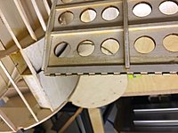
A quick update on progress. I finally made the move to cut of the rib ends and make new parts to go in the scale position. I made a template and cut them to look as scale as possible. I decided to add a layer of thin ply on top of those ribs since it's the same that would have been added to the underside if I hadn't gone the scale route.
10-16-2017, 12:30 PM
#19
Thread Starter
Join Date: Sep 2014
Location: Scottsdale, AZ
Posts: 169
Likes: 0
Received 0 Likes
on
0 Posts
I also added wood blocks on top and below the wing tube. I'm planning to have the wing bolts come from on top - I saw that in a thread and thought it was a good idea (cover with a gas cap).
01-23-2018, 04:51 PM
#20
Thread Starter
Join Date: Sep 2014
Location: Scottsdale, AZ
Posts: 169
Likes: 0
Received 0 Likes
on
0 Posts
Spending the holidays back in San Diego, I managed to get a few more things done on the build. I added the piano hinge to the flap and sandwiched it under a layer of thin ply. Can anyone explain to me why the piano hinge is the go-to for the SBD? I must be lost, but it's not scale so and it's a real pain to work with these things. I recall Sam writing how fun it was to pull the wire out. Yah, I agree. Works better with a .031" wire. Anyway, I'd be interested in hearing more about the genesis of piano hinges on RC planes.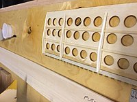
01-23-2018, 04:57 PM
#21
Thread Starter
Join Date: Sep 2014
Location: Scottsdale, AZ
Posts: 169
Likes: 0
Received 0 Likes
on
0 Posts
I also set up the hinges for the gunner's trough. I hope I didn't open a can of worms by adding this feature. The finished center flap is temporarily screwed in place. I plan to add epoxy. I'm also rethinking the bell crank system and replacing it with 2 servos. I think Sam used just 1 servo for the center flap. Any opinions would be welcomed. Once I make a final decision, I can add in the web at the TE.
01-23-2018, 05:06 PM
#23
Thread Starter
Join Date: Sep 2014
Location: Scottsdale, AZ
Posts: 169
Likes: 0
Received 0 Likes
on
0 Posts
I also finished the fuse sheeting for now. I've been spending a lot of time staring at the end of this fuse. I'm not sure if I should go with Sam's approach and mount 2 servos in the stab or use a long push rod and make a wire bracket like Wallace did to keep all the linkages internal. I'd like to keep the push rods all hidden to be scale, but these are under the plane anyways. Thoughts?
01-23-2018, 05:08 PM
#24
Thread Starter
Join Date: Sep 2014
Location: Scottsdale, AZ
Posts: 169
Likes: 0
Received 0 Likes
on
0 Posts
I've had the same issue. It comes and goes. I thought it had something to do with being officially logged but I don't think so. I also wish I could edit the pictures and get them rotated correctly. I didn't have this issue when I posted my previous build. Maybe someone else can help us.
01-23-2018, 05:12 PM
#25
Thread Starter
Join Date: Sep 2014
Location: Scottsdale, AZ
Posts: 169
Likes: 0
Received 0 Likes
on
0 Posts
I'd like to sheet the stab before I head back to Scottsdale. I see where Sam put in sheer webbing even though its not on the plan. I'm guessing it's probably a good idea or Sam wouldn't have bothered. But I still would like to have a plan on the elevator linkages. Let me know if there's a good thread for this other than what I found in Wallace's and Tom P's build.