


Ziroli SBD-3 Dauntless build
 08-19-2021, 03:53 PM
#101

Thread Starter
Join Date: Sep 2014
Location: Scottsdale, AZ
Posts: 169
Likes: 0
Received 0 Likes
on
0 Posts
I know it's been a while. Not sure if anyone is following along, but it's been lots of prep for finishing.

this is how the wingtip light base was finished

the outer wing panels have the all the panel lines in place. I have sprayed on primer and will let that cure before I complete the finish sanding.
I have rivets and hatches on order from Chad. So on to the fuselage.

I taped the windshield frame in place and found it worked best to add a little wax on top of the tape to make sure the icing released well.
This area is thin. I can only hope it stays in tact until I get the frame glued in to add some support.

Lots of sanding a filling required. I have the center section attached for reference to the wing panels.

I also started working on the polystyrene for the center bomb section.
this is how the wingtip light base was finished
the outer wing panels have the all the panel lines in place. I have sprayed on primer and will let that cure before I complete the finish sanding.
I have rivets and hatches on order from Chad. So on to the fuselage.
I taped the windshield frame in place and found it worked best to add a little wax on top of the tape to make sure the icing released well.
This area is thin. I can only hope it stays in tact until I get the frame glued in to add some support.
Lots of sanding a filling required. I have the center section attached for reference to the wing panels.
I also started working on the polystyrene for the center bomb section.
 08-19-2021, 03:59 PM
#102
Thread Starter
Join Date: Sep 2014
Location: Scottsdale, AZ
Posts: 169
Likes: 0
Received 0 Likes
on
0 Posts
This takes me back to the cowl and the firewall.

I added Superfil on the top as there was a bit of a step between the firewall and the top of the fuselage.

After a little more sanding, I sprayed some primer to get an idea of how things looked.

More sanding and priming. Here is the final version, sort of. I still have some areas to fill in - mostly dings or errant filing marks.
The step on the firewall is where the top of the cowl will rest. (maybe the firewall needs to be reduced in thickness???)

And the approximate fit of the cowl.
I need to work on replacing the flaps with new cut pieces from the CF layup. Also need to join them together. After that, I think I'll work on the exhaust and cutouts in the cowl for those exit points. Adding panel lines to the fuselage will provide an escape from the cowl work.
I added Superfil on the top as there was a bit of a step between the firewall and the top of the fuselage.
After a little more sanding, I sprayed some primer to get an idea of how things looked.
More sanding and priming. Here is the final version, sort of. I still have some areas to fill in - mostly dings or errant filing marks.
The step on the firewall is where the top of the cowl will rest. (maybe the firewall needs to be reduced in thickness???)
And the approximate fit of the cowl.
I need to work on replacing the flaps with new cut pieces from the CF layup. Also need to join them together. After that, I think I'll work on the exhaust and cutouts in the cowl for those exit points. Adding panel lines to the fuselage will provide an escape from the cowl work.
 08-20-2021, 04:31 PM
#104
Thread Starter
Join Date: Sep 2014
Location: Scottsdale, AZ
Posts: 169
Likes: 0
Received 0 Likes
on
0 Posts
Thanks Mike! Good to know I'm not alone. I need all the help I can get.
The next project is the cowl. Getting the fitment on the firewall set. Replacing the first version of flaps. And thinking through the servo drive set up. It's a good thing there are some other examples on how to do this.
Right before I started, I added a screw for the antenna mount.

I opted to go through the ammo hatch with a simple screw vs. on the side of the fuselage or through the front behind the firewall.
I don't envision taking the firewall on and off each time I fly.
I needed to take apart the current flaps.

I couldn't believe how easy it was to peel off the hinges.
I had these epoxied with the epoxy through the holes and on top of the hinges. I used 5 minute epoxy.
Next time it will be Hysol.

Next was securing the cowl in place.

On the bottom, I'm using a external screw with a rubber washer, I guess to avoid splitting the cowl.

I've seen FS pictures with and without a gap on the top between the cowl and the firewall.
The really old pictures, not restored planes, seemed to have a gap. So gap it is.

Even this side mount piece looks to be peeling away.
Just a matter of time. I see Hysol in it's future.
(notice the first hole I drilled - the cowl was set with too much of a gap so I pulled it in. Most likely will lop off the end of that mount when it's all done.

Here are the new cowl flaps, cut just a little bit long. I'm still not sure about the hinging.
The next project is the cowl. Getting the fitment on the firewall set. Replacing the first version of flaps. And thinking through the servo drive set up. It's a good thing there are some other examples on how to do this.
Right before I started, I added a screw for the antenna mount.
I opted to go through the ammo hatch with a simple screw vs. on the side of the fuselage or through the front behind the firewall.
I don't envision taking the firewall on and off each time I fly.
I needed to take apart the current flaps.
I couldn't believe how easy it was to peel off the hinges.
I had these epoxied with the epoxy through the holes and on top of the hinges. I used 5 minute epoxy.
Next time it will be Hysol.
Next was securing the cowl in place.
On the bottom, I'm using a external screw with a rubber washer, I guess to avoid splitting the cowl.
I've seen FS pictures with and without a gap on the top between the cowl and the firewall.
The really old pictures, not restored planes, seemed to have a gap. So gap it is.
Even this side mount piece looks to be peeling away.
Just a matter of time. I see Hysol in it's future.
(notice the first hole I drilled - the cowl was set with too much of a gap so I pulled it in. Most likely will lop off the end of that mount when it's all done.
Here are the new cowl flaps, cut just a little bit long. I'm still not sure about the hinging.
Last edited by BatteryBob; 08-20-2021 at 04:34 PM.
08-22-2021, 05:36 PM
#105
Thread Starter
Join Date: Sep 2014
Location: Scottsdale, AZ
Posts: 169
Likes: 0
Received 0 Likes
on
0 Posts
After doing some research, I realize that the gap behind the cowl is good. The SBD 1-4 is more narrow than the -5. But in this case, the reference should be in front of the firewall, not behind. The removable firewall gives the visual impression that the firewall is actually the vertical (reference) line, when it is not. So I'm good with this.

I want to make my best attempt to create a scale looking carb intake. Started by drilling holes and using the dremel.

More filing and shaping. There needs to be a surface added behind that lower cut line.

I put some packing tape on the opposite end and did a 4 layer layup of 3oz crowsfoot to create this missing surface.
I want to make my best attempt to create a scale looking carb intake. Started by drilling holes and using the dremel.
More filing and shaping. There needs to be a surface added behind that lower cut line.
I put some packing tape on the opposite end and did a 4 layer layup of 3oz crowsfoot to create this missing surface.
Last edited by BatteryBob; 08-22-2021 at 07:37 PM.
08-22-2021, 07:30 PM
#106
Thread Starter
Join Date: Sep 2014
Location: Scottsdale, AZ
Posts: 169
Likes: 0
Received 0 Likes
on
0 Posts
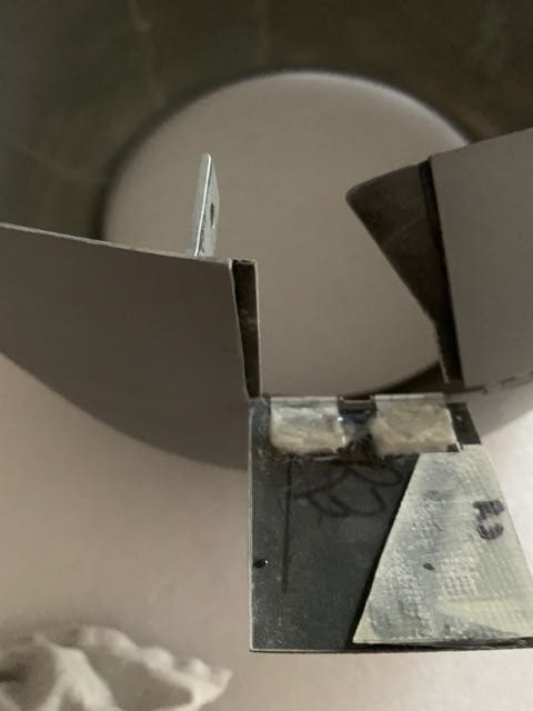
Worked on the hinges. Others seem to prove that it's best to notch in the hinge pin to the cowl. I've tried it the other way and seemed to have more binding up, so it was time to change the approach.

I used a black marker help me see what material needed to be removed.

I did this with a file, first notching out the ends. Followed by a flat file to remove the center hump without too much worry for drifting too far left or right.

Then I needed to use a small drum sander on the dremel to removed the ply I had epoxied in for the prior hinge attempt.
I want to have the end of the hinge angled so that the center pin section sits up slightly above the surface of the cowl.
My thought here is to prevent the flap from binding on the cowl edge as it rotates.
I used a black marker help me see what material needed to be removed.
I did this with a file, first notching out the ends. Followed by a flat file to remove the center hump without too much worry for drifting too far left or right.
Then I needed to use a small drum sander on the dremel to removed the ply I had epoxied in for the prior hinge attempt.
I want to have the end of the hinge angled so that the center pin section sits up slightly above the surface of the cowl.
My thought here is to prevent the flap from binding on the cowl edge as it rotates.
08-23-2021, 10:48 PM
#107
Thread Starter
Join Date: Sep 2014
Location: Scottsdale, AZ
Posts: 169
Likes: 0
Received 0 Likes
on
0 Posts
I figure if we go to all the trouble to get the wheel bays and lower side of the wing covered with rivets and hatches, it's probably worthwhile to get the nose of the plane right.

The cowl needs to be inset a bit in the area under the intake port.

I cut and shaped these G10 pieces to frame out the intake.

These were epoxied in place with Hysol and held with tape and a piece of foam to keep some pressure on the parts.

A little bit of shaping and it's beginning to look good.

Here's where I used the layup. Plus the small part that I cut out in the 1st picture.
I added a little Superfil to a few of the low spots. I'll do some more shaping and see how things look.
The cowl needs to be inset a bit in the area under the intake port.
I cut and shaped these G10 pieces to frame out the intake.
These were epoxied in place with Hysol and held with tape and a piece of foam to keep some pressure on the parts.
A little bit of shaping and it's beginning to look good.
Here's where I used the layup. Plus the small part that I cut out in the 1st picture.
I added a little Superfil to a few of the low spots. I'll do some more shaping and see how things look.
08-25-2021, 09:49 AM
#108
Thread Starter
Join Date: Sep 2014
Location: Scottsdale, AZ
Posts: 169
Likes: 0
Received 0 Likes
on
0 Posts
Here's where the intake work on the cowl ended -
I added more filler, some more rough sanding and placed in one more baffle piece from the leftover of the layup.

Sprayed on primer to get a better look at the entire cowl surface. There is a bit of Hysol inside of these added pieces. I'm satisfied with this.

Here's the full scale reference.
Time to get the flaps attached and begin laying out the panel lines on the fuselage.
I added more filler, some more rough sanding and placed in one more baffle piece from the leftover of the layup.
Sprayed on primer to get a better look at the entire cowl surface. There is a bit of Hysol inside of these added pieces. I'm satisfied with this.
Here's the full scale reference.
Time to get the flaps attached and begin laying out the panel lines on the fuselage.
08-25-2021, 12:55 PM
#109
Thread Starter
Join Date: Sep 2014
Location: Scottsdale, AZ
Posts: 169
Likes: 0
Received 0 Likes
on
0 Posts
A few more pictures from the inside of the cowl for those interested -

I still need to figure out how or if I want this air flowing in. If it aides the carburator, cool.
But I also know that engine temp is an issue and why most include baffles around the engine. I plan to do the same.
Please comment if you have any experience with routing air back to the carb or if it's even necessary (engine is a GT-80).
Ok, I know air is necessary, just not sure if a directed/pressure supply is too much.

From the front side. The lip on the FS version wraps around and matches the inset section. But here, that is hard to do.
I still need to figure out how or if I want this air flowing in. If it aides the carburator, cool.
But I also know that engine temp is an issue and why most include baffles around the engine. I plan to do the same.
Please comment if you have any experience with routing air back to the carb or if it's even necessary (engine is a GT-80).
Ok, I know air is necessary, just not sure if a directed/pressure supply is too much.
From the front side. The lip on the FS version wraps around and matches the inset section. But here, that is hard to do.
08-26-2021, 07:12 PM
#110
Thread Starter
Join Date: Sep 2014
Location: Scottsdale, AZ
Posts: 169
Likes: 0
Received 0 Likes
on
0 Posts
More layups. Got the flap hinges attached to the cowl and then added the flaps. I did it in this order to make sure the hinge pins were all in a line and inside the notched areas in the cowl.

While I didn't mount the cowl on for this shot, I was mainly checking the outside alignment.

The flaps move freely. They are fitting close on the top and bottom sides.
I will likely need to a little sanding.

Added packing tape and did a 1 layer CF - 2 layer FG layup for the sliding section that will be added to the center flap.
I plan to use the old flaps to create the pockets in the top and bottom flaps.
Up next is the connecting parts and the servo/drive set up. And marking off the fuselage. This all moves so slowly.
While I didn't mount the cowl on for this shot, I was mainly checking the outside alignment.
The flaps move freely. They are fitting close on the top and bottom sides.
I will likely need to a little sanding.
Added packing tape and did a 1 layer CF - 2 layer FG layup for the sliding section that will be added to the center flap.
I plan to use the old flaps to create the pockets in the top and bottom flaps.
Up next is the connecting parts and the servo/drive set up. And marking off the fuselage. This all moves so slowly.
08-30-2021, 09:57 AM
#111
Thread Starter
Join Date: Sep 2014
Location: Scottsdale, AZ
Posts: 169
Likes: 0
Received 0 Likes
on
0 Posts
Spent a few hours over the weekend adding the connecting slides between each group of 3 cowl flaps. I considered what boB did (a great reference) but went the route I was more familiar with (on my Corsair).

The #2 flap got this piece attached that adds side wings that will slide into flaps #1 and #3.

Here is an example of the slide pockets. I used left over pieces from the flaps to act as the spacer.
The original flaps pieces were cut and used as the top piece. It's important to have the right orientation/curvature of these parts.

On the bottom edge of flap #3, this lip was added (here the flap is closed)
Flap is shown open.

On the top side, I'll need to make a really small layup to get a piece that conforms to the curve on the inside.
The #2 flap got this piece attached that adds side wings that will slide into flaps #1 and #3.
Here is an example of the slide pockets. I used left over pieces from the flaps to act as the spacer.
The original flaps pieces were cut and used as the top piece. It's important to have the right orientation/curvature of these parts.
On the bottom edge of flap #3, this lip was added (here the flap is closed)
Flap is shown open.
On the top side, I'll need to make a really small layup to get a piece that conforms to the curve on the inside.
09-06-2021, 05:03 PM
#112
Thread Starter
Join Date: Sep 2014
Location: Scottsdale, AZ
Posts: 169
Likes: 0
Received 0 Likes
on
0 Posts
a little more on flaps

this is looking at the plane, inverted while I'm working on the bottom. The lowest of the 3 flaps is not quite closing tight.

The edges of the "pocket" for the slider on the adjacent flap needed to be sanded to fit the profile of the cowl ring.
I have yet to work on the servo mount and connectors. I'll work that in as I get burned out on the fuselage panels.
this is looking at the plane, inverted while I'm working on the bottom. The lowest of the 3 flaps is not quite closing tight.
The edges of the "pocket" for the slider on the adjacent flap needed to be sanded to fit the profile of the cowl ring.
I have yet to work on the servo mount and connectors. I'll work that in as I get burned out on the fuselage panels.
09-06-2021, 05:49 PM
#113
Thread Starter
Join Date: Sep 2014
Location: Scottsdale, AZ
Posts: 169
Likes: 0
Received 0 Likes
on
0 Posts
The process of laying out the lines for rivets and panels is time consuming (for me at least). Since the plane is not exactly to scale, I found that I had to make choices to keep things reasonably spaced and in keeping with the scale references. I used pencil for the longest time and until I thought everything made sense.
I haven't found specific examples of how to transfer lines from a print. I used a combination of a laser, straight edge and soft straight edge and string to help layout the lines. As you layout the former lines, I found that if I keep referencing off the firewall, the last several formers would be stacked too close. Kind of like progression error. So I worked off from immovable references like the steps on the side, cockpit, stabilizer etc.

Here is how I used string on the bottom curves of the fuselage.
It's always a little bit of a struggle to make sure both sides are going to line up when the meet at the top or bottom.

another view using the string.

I used the laser to see if the central panel line (not to be confused with the prop centerline) would
pass under the first step and over the second and also tie off under the stabilizer in the right position.

I will need to do some buildup to create the gun covers.

Several lines forward of the side vents are actually butt joints.

Most of the lines for the panels have been drawn. More lines will be needed for rivets.
I haven't found specific examples of how to transfer lines from a print. I used a combination of a laser, straight edge and soft straight edge and string to help layout the lines. As you layout the former lines, I found that if I keep referencing off the firewall, the last several formers would be stacked too close. Kind of like progression error. So I worked off from immovable references like the steps on the side, cockpit, stabilizer etc.
Here is how I used string on the bottom curves of the fuselage.
It's always a little bit of a struggle to make sure both sides are going to line up when the meet at the top or bottom.
another view using the string.
I used the laser to see if the central panel line (not to be confused with the prop centerline) would
pass under the first step and over the second and also tie off under the stabilizer in the right position.
I will need to do some buildup to create the gun covers.
Several lines forward of the side vents are actually butt joints.
Most of the lines for the panels have been drawn. More lines will be needed for rivets.
09-07-2021, 03:07 PM
#114
Thread Starter
Join Date: Sep 2014
Location: Scottsdale, AZ
Posts: 169
Likes: 0
Received 0 Likes
on
0 Posts
Taking a break from the panel lines - I've got the fuselage upside down and I'm working from the back to the front - it was time to work on the center bomb section.

I made this out of 3 sections of polystyrene. The section, per the Ziroli design, is close to scale.
I would have had to been more aware before I built this section if I wanted to have the moving doors.

I sketched in where the piping ran and used 1/4" PS tubing. I cut a tube in half so it would fit in the thin area.

This vaguely resembles some reference material that I have. Rivets, a few panel lines and some L channel are still needed.
I'm thinking that tubing etc will be painted zinc chromate. The inset panels will be painted same color as the wheel wells.
I made this out of 3 sections of polystyrene. The section, per the Ziroli design, is close to scale.
I would have had to been more aware before I built this section if I wanted to have the moving doors.
I sketched in where the piping ran and used 1/4" PS tubing. I cut a tube in half so it would fit in the thin area.
This vaguely resembles some reference material that I have. Rivets, a few panel lines and some L channel are still needed.
I'm thinking that tubing etc will be painted zinc chromate. The inset panels will be painted same color as the wheel wells.
09-08-2021, 12:59 PM
#115
Thread Starter
Join Date: Sep 2014
Location: Scottsdale, AZ
Posts: 169
Likes: 0
Received 0 Likes
on
0 Posts
Spending a little time on the center section.

Run CA over these parts. Had thought about glassing but it would be a mess.
Did some quick sanding to about 225 grit.

Sprayed this up with primer. Figured it will be a lot easier to sand these now versus after they are glued in place.

Cutting the polystyrene bases.
Run CA over these parts. Had thought about glassing but it would be a mess.
Did some quick sanding to about 225 grit.
Sprayed this up with primer. Figured it will be a lot easier to sand these now versus after they are glued in place.
Cutting the polystyrene bases.
09-09-2021, 09:03 AM
#116
Thread Starter
Join Date: Sep 2014
Location: Scottsdale, AZ
Posts: 169
Likes: 0
Received 0 Likes
on
0 Posts
While I'm working out some changes to the center bomb rack, I'm still trying to get a clear idea of what's going on under the stabilizer and back by the rear cone as it relates to panel lines. boB on RCSB has shown his work and it's a great reference. Yet, when I look at the analysis by Witold Jaworski, he shows some reference pictures that matches some of my books and reference material that shows some the panel lap joints are forward facing. Ok, this may be trivial, but while I'm at it, I'd like to get it right.

These panels lines appear forward of the rivets holding them in place.

I'm looking at both the one under the stab and the one just behind it. This actual picture appears to be on a "less restored" plane. Witold shows, in another picture, where the restoration process changed the cone section more significantly.
Just thought it might be useful to anyone else working on this plane with little experience like myself. I live in the San Diego N county area during the summer and had hoped to visit the Leathernecks museum to check out their SBD-1 and a somewhat rare F4U-5. Alas, they are closed and moving to Chino.
Oh well, no more excuses to get this done.
These panels lines appear forward of the rivets holding them in place.
I'm looking at both the one under the stab and the one just behind it. This actual picture appears to be on a "less restored" plane. Witold shows, in another picture, where the restoration process changed the cone section more significantly.
Just thought it might be useful to anyone else working on this plane with little experience like myself. I live in the San Diego N county area during the summer and had hoped to visit the Leathernecks museum to check out their SBD-1 and a somewhat rare F4U-5. Alas, they are closed and moving to Chino.
Oh well, no more excuses to get this done.
09-12-2021, 05:09 PM
#117
Thread Starter
Join Date: Sep 2014
Location: Scottsdale, AZ
Posts: 169
Likes: 0
Received 0 Likes
on
0 Posts
Onto the fuselage panel lines. If you're like me, you haven't done a lot of this. I had a little warm up experience on 2 foamies T-28's that I covered with glass and the VQSBD that I recovered. Apparently that's not enough experience.
I was using/trying some 3M and Tamiya fine line tape that is supposed to handle small curves. The curves found on the stabilizer might be too much. Or it could be me.
I kept finding the tape lifting due to the stress of the curves. Not to mention the difficulty of getting 3-4 consecutive layers lined up well. So I came across a better method that probably everyone else has figured out, but if you're a newbie like myself, you might appreciate this hack.
Here are the steps. First, get rid of all the tape that keeps lifting off. Then...

I used a fine point Sharpie to mark the panel line on the plane.
One layer of green 3M tape, nice and flat, and you get see this panel line well enough to trace on top of the tape.
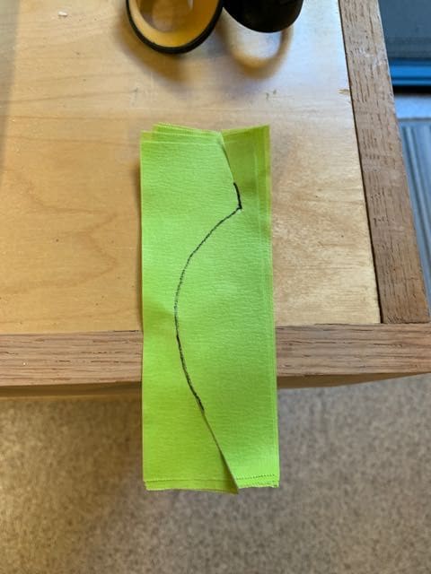
Take that piece off from the plane and add 3 more layers underneath.
Then cut along the line. I don't think I can get 4 layers and that curve doing them one at a time.

Back to the plane. I did this for each side and then alternated the ends on the top where the 2 sides meet.
Use an Xacto blade to trim if you're not satisfied with the lines. Just be careful.

I did this for the caps on the wing tips. This way the tape can lay flat without stress.
And that green tape has great tack but does not pull up on anything like primer or existing panel lines (just make sure everything has cured).

Still use blue tape for the straight, easy stuff.

Working my way from the back to the front. Keeping track of how the panels overlap each other.
The yellow icing is pretty easy to trim with a sharp blade, but can chip or flake easily before it's really cured.
One other project I'd like to get some traction on before putting this project on hold is the exhaust. I plan to put the engine back on and make a model of the pipes. A friend of mine is trying to convince me to let him help me make these out of SS rather than all of the copper fittings I purchased.
I was using/trying some 3M and Tamiya fine line tape that is supposed to handle small curves. The curves found on the stabilizer might be too much. Or it could be me.
I kept finding the tape lifting due to the stress of the curves. Not to mention the difficulty of getting 3-4 consecutive layers lined up well. So I came across a better method that probably everyone else has figured out, but if you're a newbie like myself, you might appreciate this hack.
Here are the steps. First, get rid of all the tape that keeps lifting off. Then...
I used a fine point Sharpie to mark the panel line on the plane.
One layer of green 3M tape, nice and flat, and you get see this panel line well enough to trace on top of the tape.
Take that piece off from the plane and add 3 more layers underneath.
Then cut along the line. I don't think I can get 4 layers and that curve doing them one at a time.
Back to the plane. I did this for each side and then alternated the ends on the top where the 2 sides meet.
Use an Xacto blade to trim if you're not satisfied with the lines. Just be careful.
I did this for the caps on the wing tips. This way the tape can lay flat without stress.
And that green tape has great tack but does not pull up on anything like primer or existing panel lines (just make sure everything has cured).
Still use blue tape for the straight, easy stuff.
Working my way from the back to the front. Keeping track of how the panels overlap each other.
The yellow icing is pretty easy to trim with a sharp blade, but can chip or flake easily before it's really cured.
One other project I'd like to get some traction on before putting this project on hold is the exhaust. I plan to put the engine back on and make a model of the pipes. A friend of mine is trying to convince me to let him help me make these out of SS rather than all of the copper fittings I purchased.
09-16-2021, 06:43 PM
#118
Thread Starter
Join Date: Sep 2014
Location: Scottsdale, AZ
Posts: 169
Likes: 0
Received 0 Likes
on
0 Posts
It's been slow going. I have not found the way to work with the icing prior to full cure. At least not to my satisfaction.
I finished the underside of the stabilizer and fuselage, for the most part.

I'm only doing the panel lines from the rear to about mid fuselage.

here is the top side of the stabilizer.
I use a Ryobi detail sander to blend the icing. I'm using 240 sandpaper. I find that while it takes a lot longer, I don't have to worry about deep grooves from 80 or 100 grit.
I finished the underside of the stabilizer and fuselage, for the most part.
I'm only doing the panel lines from the rear to about mid fuselage.
here is the top side of the stabilizer.
I use a Ryobi detail sander to blend the icing. I'm using 240 sandpaper. I find that while it takes a lot longer, I don't have to worry about deep grooves from 80 or 100 grit.
09-20-2021, 04:37 PM
#119
Thread Starter
Join Date: Sep 2014
Location: Scottsdale, AZ
Posts: 169
Likes: 0
Received 0 Likes
on
0 Posts
So in all my brilliance, I totally messed up the panels on the tail. The good news is that it's not like starting all over.
Here's the issue:

The panel to the rear is supposed to extend down past the bottom of the panel in front.

I sanded that overlapping corner until the step in the panels was gone. And the tape outlines the way the rear panel should run.

Up above, the panel will go up and over the to other side.

The icing fills out the new area.

And then the forward panel is redone and all is well.

The 1st and 2nd panels share a common bottom line. At least according to my reference docs and pictures.

I added primer to the under belly bomb drop area. Faux doors were made.
Here's the issue:
The panel to the rear is supposed to extend down past the bottom of the panel in front.
I sanded that overlapping corner until the step in the panels was gone. And the tape outlines the way the rear panel should run.
Up above, the panel will go up and over the to other side.
The icing fills out the new area.
And then the forward panel is redone and all is well.
The 1st and 2nd panels share a common bottom line. At least according to my reference docs and pictures.
I added primer to the under belly bomb drop area. Faux doors were made.
09-28-2021, 08:33 PM
#120
Thread Starter
Join Date: Sep 2014
Location: Scottsdale, AZ
Posts: 169
Likes: 0
Received 0 Likes
on
0 Posts
I don't know where this summer has gone. I've been making more progress on the fuselage panel lines. Getting down to the front end.

Lots of details on the back end. I use a small flat, square file to trim the edges.

This forward panel on the fuselage is a bit unique. The top and front are not facing the typical down, back direction.

I've seen this done a few different ways, but this is how I've seen it on a thread where a SBD was repainted and also in a few snapshots on an original.

So this might be one panel I got right. The main thing is "be consistent!" - that is top to bottom or side to side.
Time will be running out and I will be leaving this build for another stretch of time. Had hoped to get to the rivets. Chad has them ready for me, but I'm not ready for him.
So the next installment will be rivets and canopy work.
Lots of details on the back end. I use a small flat, square file to trim the edges.
This forward panel on the fuselage is a bit unique. The top and front are not facing the typical down, back direction.
I've seen this done a few different ways, but this is how I've seen it on a thread where a SBD was repainted and also in a few snapshots on an original.
So this might be one panel I got right. The main thing is "be consistent!" - that is top to bottom or side to side.
Time will be running out and I will be leaving this build for another stretch of time. Had hoped to get to the rivets. Chad has them ready for me, but I'm not ready for him.
So the next installment will be rivets and canopy work.
10-03-2021, 06:54 PM
#121
Thread Starter
Join Date: Sep 2014
Location: Scottsdale, AZ
Posts: 169
Likes: 0
Received 0 Likes
on
0 Posts
Some last photos as this build goes on hiatus. I have a few more vertical panel lines to add and I'm still comparing pictures from books, other builds and a few walk arounds and the one repainting of a SBD-5. The last one is useful because they have the plane stripped and the panel lines are even more obvious.

I guess it will be rivets and painting next summer. The panel lines took a lot more time using the yellow icing vs. building primer.

Still have some center wing detail and bomb drops for the wings.

The cowl will need panel lines and some raised detail around the gun troughs.
I guess it will be rivets and painting next summer. The panel lines took a lot more time using the yellow icing vs. building primer.
Still have some center wing detail and bomb drops for the wings.
The cowl will need panel lines and some raised detail around the gun troughs.
07-04-2022, 07:38 PM
#123
Thread Starter
Join Date: Sep 2014
Location: Scottsdale, AZ
Posts: 169
Likes: 0
Received 0 Likes
on
0 Posts
I'm back at it for the summer again. Finished what I hope are the last of the panel lines. Turned my attention back to the front windshield.

I didn't really like this version of the frame. After seeing how boB did this (over on RCSB), I decided to follow his steps.

I cut 4 pieces of carbon fiber strip @ .25" width. 30 minute epoxy with a touch of alcohol was used to laminate the strips.

Using this foam board as a form, and applying Gorilla tape along the inside edges, I was able to place the strips in while the epoxy cured.

Taped and weighted down on some plastic wrap
I didn't really like this version of the frame. After seeing how boB did this (over on RCSB), I decided to follow his steps.
I cut 4 pieces of carbon fiber strip @ .25" width. 30 minute epoxy with a touch of alcohol was used to laminate the strips.
Using this foam board as a form, and applying Gorilla tape along the inside edges, I was able to place the strips in while the epoxy cured.
Taped and weighted down on some plastic wrap
07-04-2022, 07:44 PM
#124
Thread Starter
Join Date: Sep 2014
Location: Scottsdale, AZ
Posts: 169
Likes: 0
Received 0 Likes
on
0 Posts
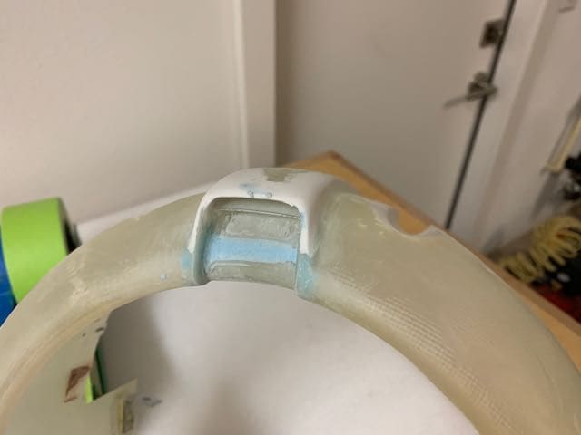
The final product -

I cut a slit for the frame to insert using a simple Xacto saw. You need to allow a little gap between the carbon frame and the turned up lip that runs around the top of the fuselage - to fit in the canopy and the frame.

I'll use the canopy plus the frame to set the overall height. I also checked this against the drawing and it looks good.
I cut a slit for the frame to insert using a simple Xacto saw. You need to allow a little gap between the carbon frame and the turned up lip that runs around the top of the fuselage - to fit in the canopy and the frame.
I'll use the canopy plus the frame to set the overall height. I also checked this against the drawing and it looks good.
07-04-2022, 07:55 PM
#125
Thread Starter
Join Date: Sep 2014
Location: Scottsdale, AZ
Posts: 169
Likes: 0
Received 0 Likes
on
0 Posts
Before I get to the rivets, I need to get on with the wing seam cover. This is also a copy of how boB did his.
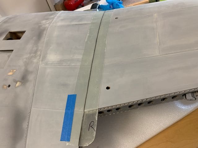
The is a layup of 1.4 and 3.4 glass. Shown after curing and removal of plastic wrap. Still not cut to width.

This is .25" half round. I layed down side by side pieces of .060" x .188", then a layer of side by side .040" x .156". I used a heat gun to set a bend in the individual layers so the parts would more easily glue to the layup and not fight me.

It took me a while to figure out where to get the half round. I messaged boB and he passed on his source - Plastruct. Like boB had mentioned, the half round definitely requires some heat.

I plan to sand and shape this strip to remove the steps and get a shape closer to the scale version.

The top side is done and wraps around the bottom. Just a small section to complete.
I applied some more primer on the yellow glaze panel areas. Time for inspection and more sanding and likely more priming before I start adding hatches and rivets.
The is a layup of 1.4 and 3.4 glass. Shown after curing and removal of plastic wrap. Still not cut to width.
This is .25" half round. I layed down side by side pieces of .060" x .188", then a layer of side by side .040" x .156". I used a heat gun to set a bend in the individual layers so the parts would more easily glue to the layup and not fight me.
It took me a while to figure out where to get the half round. I messaged boB and he passed on his source - Plastruct. Like boB had mentioned, the half round definitely requires some heat.
I plan to sand and shape this strip to remove the steps and get a shape closer to the scale version.
The top side is done and wraps around the bottom. Just a small section to complete.
I applied some more primer on the yellow glaze panel areas. Time for inspection and more sanding and likely more priming before I start adding hatches and rivets.