


How To: Installing the Henntec tensioner in a Heng Long Jagdpanther.
 01-21-2018, 02:44 PM
#1
Note: Click on any picture for a larger version.
So I have a Heng Long Jagdpanther. I did a custom paint job on it and added photo-etched engine grill covers. This one was my second Jagdpanther and I got the metal upgrade version with metal drive and idler wheels, and metal tracks. I think it turned out pretty good compared to a stock Heng Long Jagpanther:

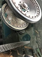
Sadly, this tank would frequently throw tracks. The tracks would jump the idler:
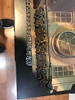
The culprit is two-fold. First, there is no way to adjust the track tension short of adding or removing links. Second, the Heng Long idler wheel has a lot of slop in it because it does not use a real bearing and axle. Instead, it has a self-tapping plastic shoulder screw that kinda-sorta fits into a pocket in the wheel hub. But there is enough play that the wheel wobbles a lot on its "axle".
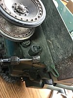
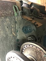
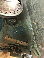
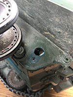
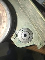
Here you can see the fixed plastic boss on the Heng Long Jagdpanther hull, and the threads of the self-tapping shoulder screw "axle":

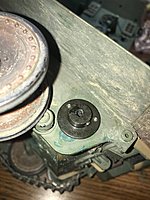
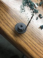
Here you can see the actual screw that functions as an axle:

So, I decided to look into installing track tensioners. After doing some googling, it seemed like the Henntec tensioners were held in high regard. I bought mine from Forgebear Tanks:
https://www.forgebeartanks.com/store...Heng_Long.html
They make tensioners for different kinds of the same kind of tank, so make sure you get one for your tank. This one is for the stock Heng Long tank.
The instructions come in German, and even with the aid of Google Translate I found them difficult to follow until I got into the installation. I figured I'd make a pictorial essay of how I did my installation. If it deviates from the correct method of installation it's because I was winging it.
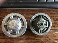
Because the Heng Long idler had no bearings, I decided to order Taigen idlers from Imex. They come with real bearings and an axle that fits perfectly in the Henntec tensioner:
PANTHER G/F AUSF G METAL DRIVE & IDLER WHEEL SET
Sadly you cannot buy the idlers separately that I found, you have to buy a drive and idler set, so I now have some spare Taigen drive wheels. I did not want to replace my drive wheels as I was not sure they were a direct fit to the stock Heng Long tracks. Plus I didn't want to paint them.
The Taigen idlers were slightly larger than the Heng Long idlers, but this does not make any functional difference. I do not know which is more scale correct.
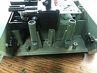
The first order of business is to remove the bosses on the stock Heng Long hull. I used a Dremel tool and a high speed cutter to make quick work of it. When I got down near flush, I used a file to smooth it all off:
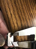
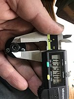
Next, we have to figure out where to drill the through-hole for the main tensioner axle. To do this, I measured the center-to-center of between the main axle of the tensioner arm and the hole where the idler wheel goes. I assumed that the current stock location of the idler was a good fixed reference (the idler should be positioned about where it originally was), and then I used the original two holes to find the "11 o'clock" position mentioned in the Henntec instructions.
Measuring:
Marking on the hull:
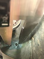
Unfortunately, where we need to drill is basically right on the edge of the hole in the tank. This is very hard because if you try and drill like this the drill bit will naturally fall into the existing hole and be off-center. Normally in wood working what you do at this point is glue a dowel rod into the hole and sand it flush, so you can drill a new hole in what seems like virgin material. But I did not want to try do that here. So instead I took a cone-shaped high speed cutter with the Dremel tool and simply enlarge the existing hole while pushing the bit away from it until I had created a new, bigger hole centered where it was supposed to be. Then, I drilled the the correct size using a drill.
Measuring for the right sized drill bit to use:
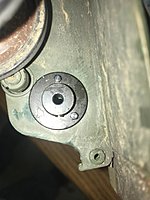
The main axle hole now drilled out:
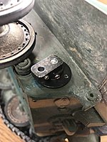
The tensioner hub set in place:
It is important to note that the tensioner hubs are not identical - there are left and right pieces. You want to position the tensioner hub on each side of the tank so that the set screw in the hub points rearwards. This allows you to access the set screw with an Allen wrench when the tank is fully assembled so that you can adjust the tension. Same thing with the swing arm - you want its set screw to point rearwards so you can get at it.
The tensioner hub and swing arm set in place:
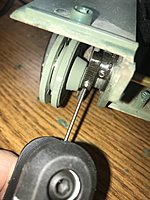
Next, I had to drill the holes for the tiny bolts that hold the tensioner hub in place. I test-fit drill bits in the holes in the hub until I found a match:
Then, I set the tensioner hub in place, positioned the hub set screw so that it was pointing exactly rearward, and I drilled out one of the mounting holes. Then, I put the bolt in place to hold the hub and stop it from rotating while I drilled the next hole:
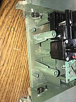
Then I set the other bolt in place:
You will find that unless you have a tiny nut driver it is very hard to get the nuts spun onto the bolts. I had to use my fingers, so I had to remove the back panel of the tank. This made it much easier to get the washers and nuts installed:
Next, I installed the brass tube that runs between the two tensioner axles. This tube basically provides rigidity between the two tensioner axles so that there is no flexing of the idler wheels. There is a small collar on one end of the brass tube, I don't know what function this serves. I tightened it down but the tube is totally trapped without it.
One thing I noticed right away is that the brass tube interferes with the top hull mounting bosses. So I ground away material to make rook for the brass axle tube:

One important note here: Don't go finish your installation at this point like I did because you can't install the back panel of the tank with the brass tube in place. So you must install the back panel first, and then put the brass tube in place and then insert the swing arms through the tensioner hubs and into the brass tube ends.
This photo shows me about to tighten the set screw for the idler axle, before the rear panel of the tank is on. I had to uninstall the swing arms and brass tube and re-install them after I put the back panel in place:
And that's it! Afterwards simply put your tracks back on.
To adjust the tension, simply loosen the set screw on the tensioner hub, then swing the idler for more or less tension, and then tighten the set screw. I swung my idlers rearward, increasing the tension, until the top tracks just barely touched the tops of the road wheels. I wanted enough "sag" for them to look realistic, while still having the track under tension.
When I went to drive my tank the first time, I was disappointed, because it threw a track almost immediately. I noticed that the tensioner had come loose on that idler. So I took inside, re-set the tension, and re-tightened the set screw. I drove it again, and the same thing happened. So I went inside and did it again, tightening the set screw as tightly as I dared do so. So far, it seems to have stayed put. I drove my tank all over the back yard through grass and leaves and everything and it never threw a track.
I think the Henntec tension adjuster is a great product. I am a little concerned about the amount of force required to set the set screw, but as long as it holds I think I will be in great shape.
Hope this helps future tank modders!
Steve
So I have a Heng Long Jagdpanther. I did a custom paint job on it and added photo-etched engine grill covers. This one was my second Jagdpanther and I got the metal upgrade version with metal drive and idler wheels, and metal tracks. I think it turned out pretty good compared to a stock Heng Long Jagpanther:
Sadly, this tank would frequently throw tracks. The tracks would jump the idler:
The culprit is two-fold. First, there is no way to adjust the track tension short of adding or removing links. Second, the Heng Long idler wheel has a lot of slop in it because it does not use a real bearing and axle. Instead, it has a self-tapping plastic shoulder screw that kinda-sorta fits into a pocket in the wheel hub. But there is enough play that the wheel wobbles a lot on its "axle".
Here you can see the fixed plastic boss on the Heng Long Jagdpanther hull, and the threads of the self-tapping shoulder screw "axle":
Here you can see the actual screw that functions as an axle:
So, I decided to look into installing track tensioners. After doing some googling, it seemed like the Henntec tensioners were held in high regard. I bought mine from Forgebear Tanks:
https://www.forgebeartanks.com/store...Heng_Long.html
They make tensioners for different kinds of the same kind of tank, so make sure you get one for your tank. This one is for the stock Heng Long tank.
The instructions come in German, and even with the aid of Google Translate I found them difficult to follow until I got into the installation. I figured I'd make a pictorial essay of how I did my installation. If it deviates from the correct method of installation it's because I was winging it.
Because the Heng Long idler had no bearings, I decided to order Taigen idlers from Imex. They come with real bearings and an axle that fits perfectly in the Henntec tensioner:
PANTHER G/F AUSF G METAL DRIVE & IDLER WHEEL SET
Sadly you cannot buy the idlers separately that I found, you have to buy a drive and idler set, so I now have some spare Taigen drive wheels. I did not want to replace my drive wheels as I was not sure they were a direct fit to the stock Heng Long tracks. Plus I didn't want to paint them.
The Taigen idlers were slightly larger than the Heng Long idlers, but this does not make any functional difference. I do not know which is more scale correct.
The first order of business is to remove the bosses on the stock Heng Long hull. I used a Dremel tool and a high speed cutter to make quick work of it. When I got down near flush, I used a file to smooth it all off:
Next, we have to figure out where to drill the through-hole for the main tensioner axle. To do this, I measured the center-to-center of between the main axle of the tensioner arm and the hole where the idler wheel goes. I assumed that the current stock location of the idler was a good fixed reference (the idler should be positioned about where it originally was), and then I used the original two holes to find the "11 o'clock" position mentioned in the Henntec instructions.
Measuring:
Marking on the hull:
Unfortunately, where we need to drill is basically right on the edge of the hole in the tank. This is very hard because if you try and drill like this the drill bit will naturally fall into the existing hole and be off-center. Normally in wood working what you do at this point is glue a dowel rod into the hole and sand it flush, so you can drill a new hole in what seems like virgin material. But I did not want to try do that here. So instead I took a cone-shaped high speed cutter with the Dremel tool and simply enlarge the existing hole while pushing the bit away from it until I had created a new, bigger hole centered where it was supposed to be. Then, I drilled the the correct size using a drill.
Measuring for the right sized drill bit to use:
The main axle hole now drilled out:
The tensioner hub set in place:
It is important to note that the tensioner hubs are not identical - there are left and right pieces. You want to position the tensioner hub on each side of the tank so that the set screw in the hub points rearwards. This allows you to access the set screw with an Allen wrench when the tank is fully assembled so that you can adjust the tension. Same thing with the swing arm - you want its set screw to point rearwards so you can get at it.
The tensioner hub and swing arm set in place:
Next, I had to drill the holes for the tiny bolts that hold the tensioner hub in place. I test-fit drill bits in the holes in the hub until I found a match:
Then, I set the tensioner hub in place, positioned the hub set screw so that it was pointing exactly rearward, and I drilled out one of the mounting holes. Then, I put the bolt in place to hold the hub and stop it from rotating while I drilled the next hole:
Then I set the other bolt in place:
You will find that unless you have a tiny nut driver it is very hard to get the nuts spun onto the bolts. I had to use my fingers, so I had to remove the back panel of the tank. This made it much easier to get the washers and nuts installed:
Next, I installed the brass tube that runs between the two tensioner axles. This tube basically provides rigidity between the two tensioner axles so that there is no flexing of the idler wheels. There is a small collar on one end of the brass tube, I don't know what function this serves. I tightened it down but the tube is totally trapped without it.
One thing I noticed right away is that the brass tube interferes with the top hull mounting bosses. So I ground away material to make rook for the brass axle tube:
One important note here: Don't go finish your installation at this point like I did because you can't install the back panel of the tank with the brass tube in place. So you must install the back panel first, and then put the brass tube in place and then insert the swing arms through the tensioner hubs and into the brass tube ends.
This photo shows me about to tighten the set screw for the idler axle, before the rear panel of the tank is on. I had to uninstall the swing arms and brass tube and re-install them after I put the back panel in place:
And that's it! Afterwards simply put your tracks back on.
To adjust the tension, simply loosen the set screw on the tensioner hub, then swing the idler for more or less tension, and then tighten the set screw. I swung my idlers rearward, increasing the tension, until the top tracks just barely touched the tops of the road wheels. I wanted enough "sag" for them to look realistic, while still having the track under tension.
When I went to drive my tank the first time, I was disappointed, because it threw a track almost immediately. I noticed that the tensioner had come loose on that idler. So I took inside, re-set the tension, and re-tightened the set screw. I drove it again, and the same thing happened. So I went inside and did it again, tightening the set screw as tightly as I dared do so. So far, it seems to have stayed put. I drove my tank all over the back yard through grass and leaves and everything and it never threw a track.
I think the Henntec tension adjuster is a great product. I am a little concerned about the amount of force required to set the set screw, but as long as it holds I think I will be in great shape.
Hope this helps future tank modders!
Steve
 01-21-2018, 05:23 PM
#2
Sadly, my tensioners keep slipping, and when the tracks lose tension, the tracks jump. I can't figure out how they are jumping given how hard it is to get them to jump back over it again to fix it!
Steve
Steve
 01-21-2018, 09:45 PM
#5
Even with slack tracks if your alignments good.you should be fine. One way to stop your tensioner slipping is use cap head bolts, large flat area on the shaft and you and use a bigger Allen key so.get more torque on them than what it comes with.
01-21-2018, 10:22 PM
#6
I've sold a ton of HennTec idlers in the last three years and never had a complaint. Only thing I can figure is something ain't kosher in the installation but can't quite see what.
For those of you who don't want to pay the confiscatory Post from EU/UK, here's the link for HennTec on my site, warehouse run by our resident genius, Daryl Turner:
HennTec Idler Systems ? ETO armor
For those of you who don't want to pay the confiscatory Post from EU/UK, here's the link for HennTec on my site, warehouse run by our resident genius, Daryl Turner:
HennTec Idler Systems ? ETO armor
01-22-2018, 05:09 AM
#7
I got to thinking about it and I suppose that it could be alignment, and then when the track starts to jump and the horns get up on top of the idler there is enough force that it is just cranking the idler out of tension. Because it takes a hell of a lot of force to get the track to re-jump into position - the track hits the bottom of the tank fender and there is not enough clearance for the horns to pass over the idler even when the idler is swung down as low as it goes.
I installed the wheels bottomed out on the tensioner arm, so they cannot move further inward. But since the track wants to jump outward, then maybe the idlers need to move outward? But I think it's the force on the tracks during turning when they jump. The tracks are being pulled away from the tank when turning as they drag on the ground, is my guess.
I'll check alignment tonight.
Steve
01-23-2018, 03:44 PM
#8
OK I pulled the tracks tonight, and sure enough, Yellowshaker was right. The track that was continuously jumping had an idler wheel that was about 3/16" out of alignment with the rest of the road wheels. Strangely, the other side was fine. I pulled the tensioner out of it's hub until the idler was in correct alignment, tightened everything back down, and took her for a spin.
I started out easy, nothing to stressful. But then I opened it up to full throttle, doing turns in dirt and grass, and even did super spins, and everything worked fine. No tracks thrown.
I think before it was not the tensioner losing tension, I think what was happening is the track horn jumped onto the outer rim of the idler wheel, jamming the track between the idler and the tank fender. Since there was not enough room there for the track to fit, the track applied a tremendous amount of force on the idler swing arm, forcing it down and thus causing the track to lose tension. The little set screw simply could not resist the force imparted by the wedged track.
But it seems with correctly aligned idlers, the system holds up just fine.
I'm very excited to have a reliable tank to run around now!
Now I'm going to custom-up my son's stock Heng Long Jagdpanther and give it the works, too!
Steve
01-24-2018, 10:02 PM
#9

Hello,
when i look at the first pictures,i can see that the installation is not right.
The position is not right,in the manual you cansee, how to find the right position.
regards,Guido
when i look at the first pictures,i can see that the installation is not right.
The position is not right,in the manual you cansee, how to find the right position.
regards,Guido
01-25-2018, 06:34 AM
#10
when i look at the first pictures,i can see that the installation is not right.
The position is not right,in the manual you cansee, how to find the right position.
The position is not right,in the manual you cansee, how to find the right position.
Can you elaborate in what way the position is not right?
Steve
01-25-2018, 11:15 PM
#12

First "maillemaker's" alignment issue seems pretty clear as illustrated in the first photo he posted, see that same photo below, but now circled in red.
As to "tomhugill's" point, he is correct, and offered the same working tip over a year ago at either rctankwarfare or rctankregiment.
I did file a flat spot as he recommended, that allowed for a better matting surface for the set screw to grip to and hold everything in place.
That modification worked great and I still used the kit set screws.
My issue was that the scale Kenny Kong metal tracks are exceptionally heavy, per the last photo below. The Tamiya Leopard 1A4 Henntech system from ETO Armor was not
strong enough in stock configuration to do the job. Resident Genuis and Engineer Daryl Turner even told me so, the stock HennTec System would not be strong enough to tension and
hold the heavy metal tracks that I choose to run!
"tomhugill's" recommendation fixed the issue.
John
.
01-26-2018, 07:38 AM
#13
First "maillemaker's" alignment issue seems pretty clear as illustrated in the first photo he posted, see that same photo below, but now circled in red.
I did file a flat spot as he recommended, that allowed for a better matting surface for the set screw to grip to and hold everything in place.
Presumably, though, once you get witness marks on the shaft where your set screw is biting you can accurately grind a flat spot where you need it?
Steve
01-26-2018, 08:17 AM
#14
“Presumably, though, once you get witness marks on the shaft where your set screw is biting you can accurately grind a flat spot where you need it?”
True, Tom’s flat spot solution is working on my Leo 1 for over a year now.
 Sorry about the photo thing
True, Tom’s flat spot solution is working on my Leo 1 for over a year now.
Sorry about the photo thing


