


1/7 Scale Blackburn Buccaneer All Composite Scratch Build
 12-23-2018, 10:52 PM
#151

Gary
Yes, I’m very lucky and live 25 minutes away, it’s been a regular spot for my family, my ‘bonus’ daughter would even request visits there when it was raining at weekends, over going to a child’s play centre. It’s had a huge refit for our 100th anniversary RAF year a few aeroplanes from other stores and many better positioned to look at. Get stuck again ;-)
Paul, I only had my phone with me, but knew you had struggled with info on the screen area. If you need specific detail on something let me know, it’s no chore to go and photo something.
Have a happy Xmas all
 12-28-2018, 06:45 PM
#152

Dave,
Thanks for the offer of photos. Appreciate the support and advice.
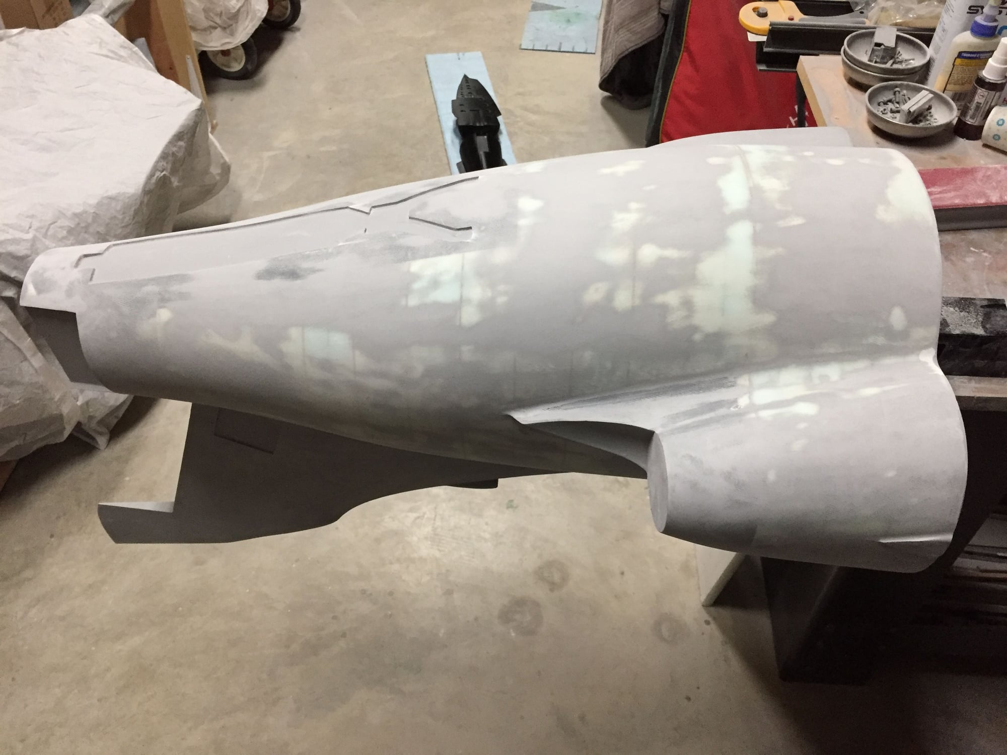
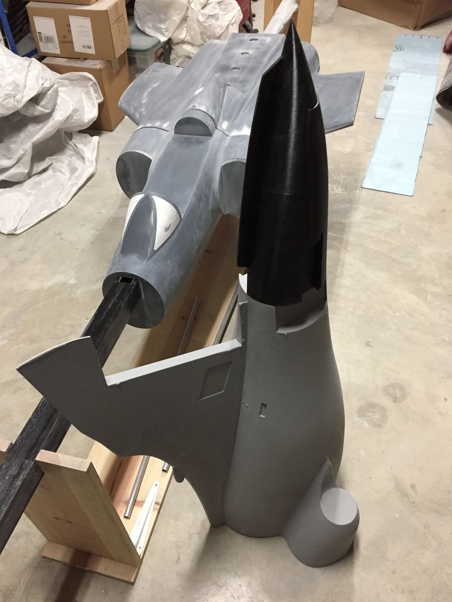
Still making progress on the fuselage plugs. Sanded the first coat of Duratec on the center fuselage and hatches and blended the front and center plug sections. Both are now ready for a final coat of Duratec.
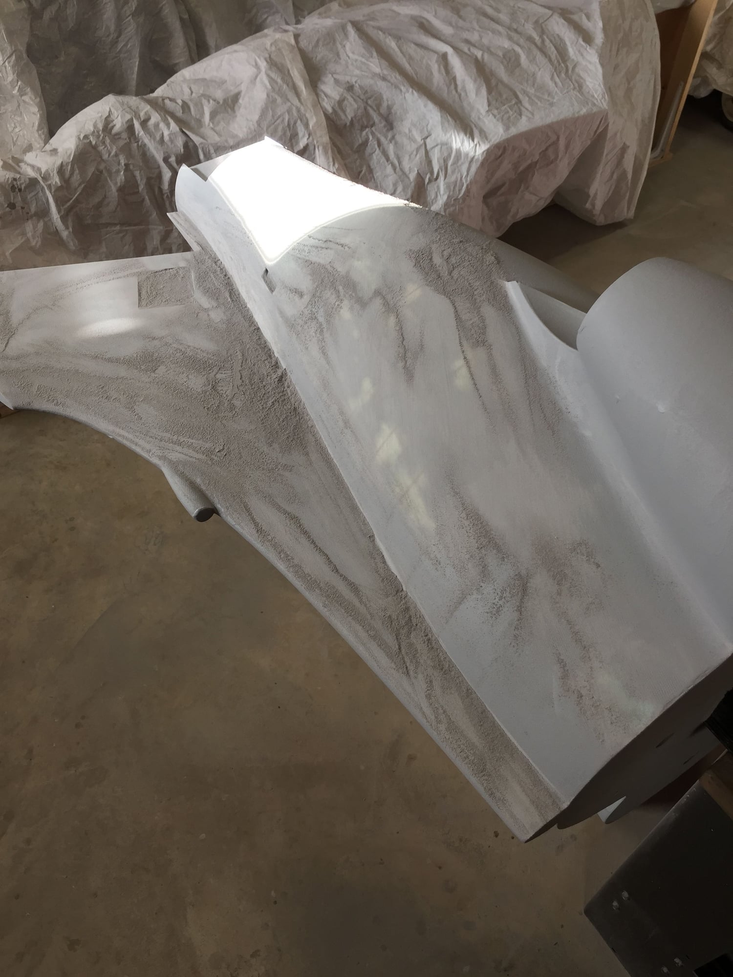
Started to rub down the initial basic primer and micro-balloon coat on the rear fuselage section.
Paul
Thanks for the offer of photos. Appreciate the support and advice.
Still making progress on the fuselage plugs. Sanded the first coat of Duratec on the center fuselage and hatches and blended the front and center plug sections. Both are now ready for a final coat of Duratec.
Started to rub down the initial basic primer and micro-balloon coat on the rear fuselage section.
Paul
12-28-2018, 06:50 PM
#153
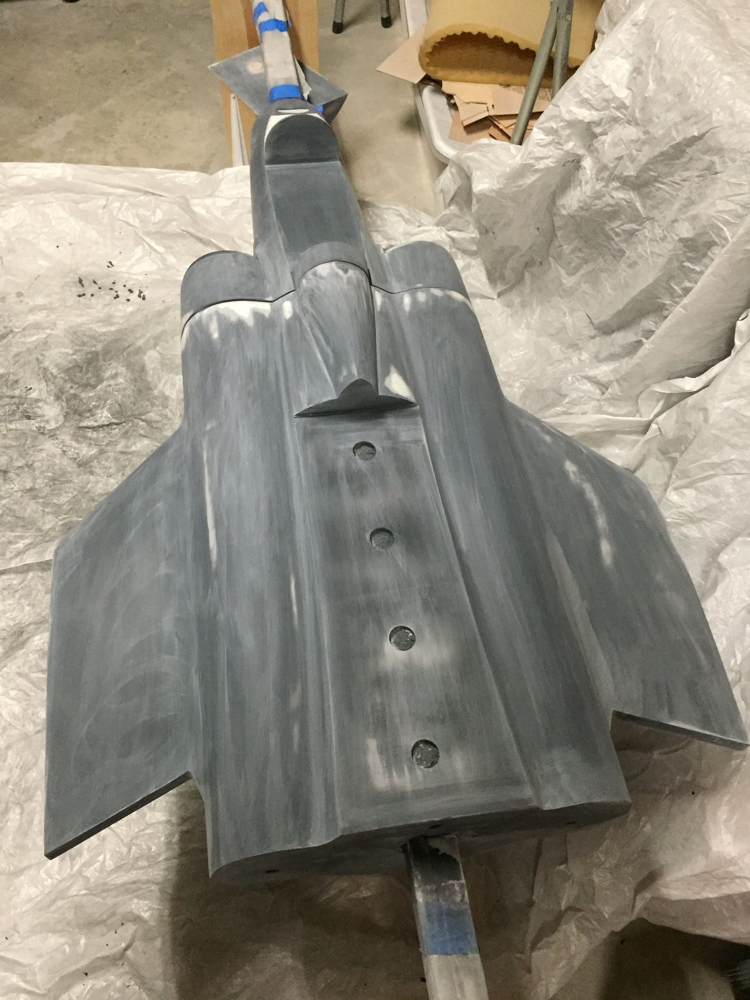
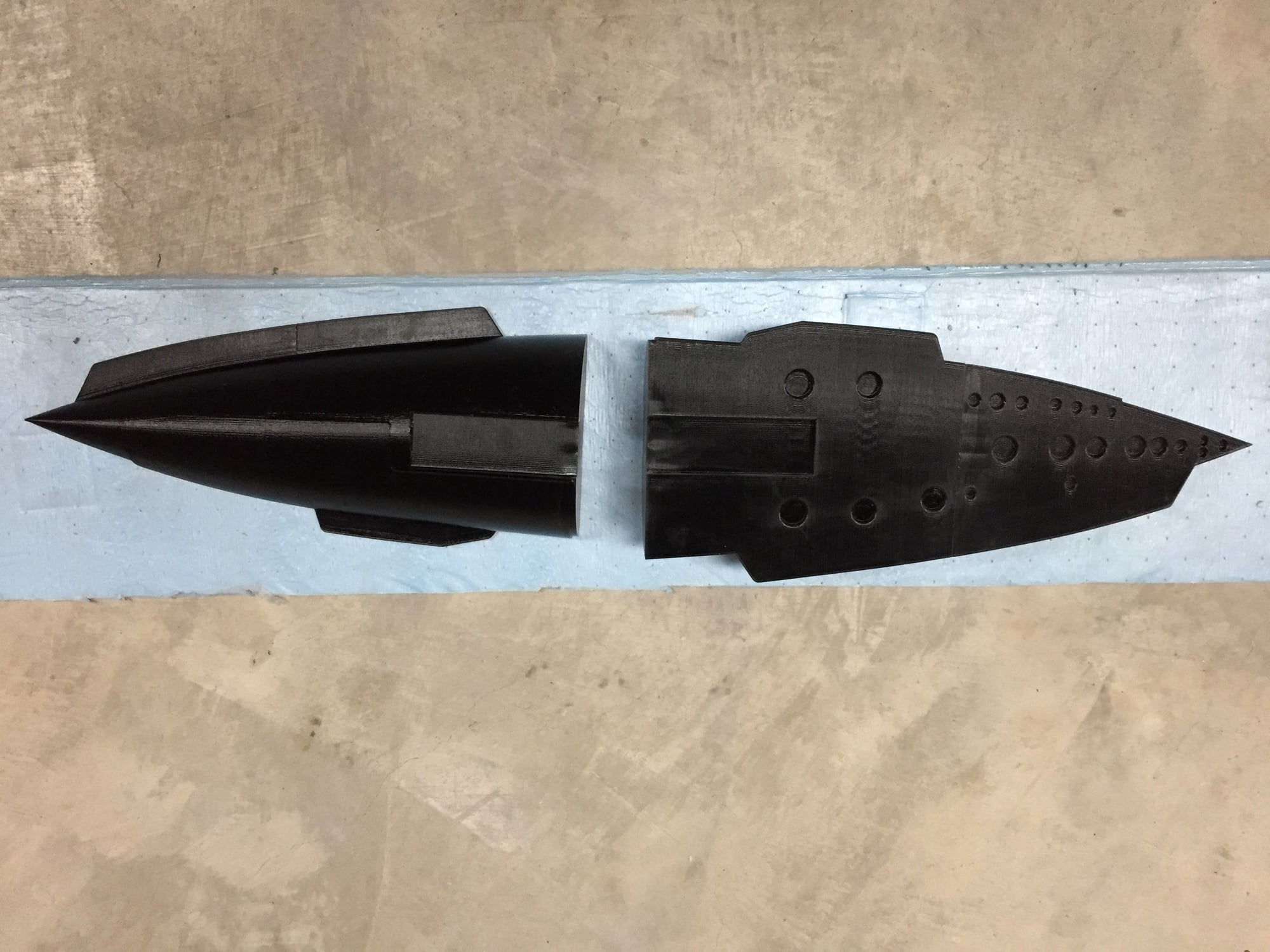
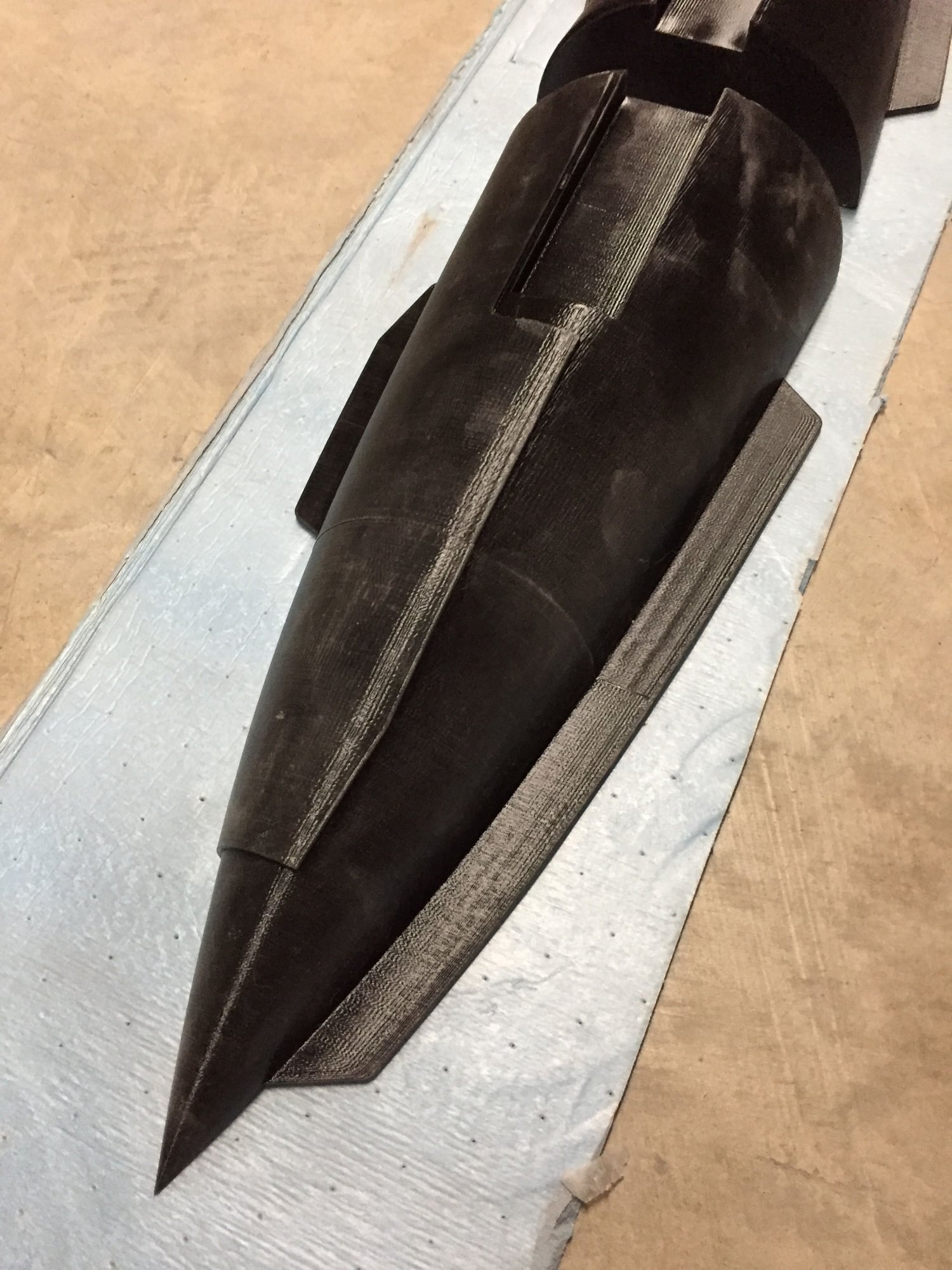
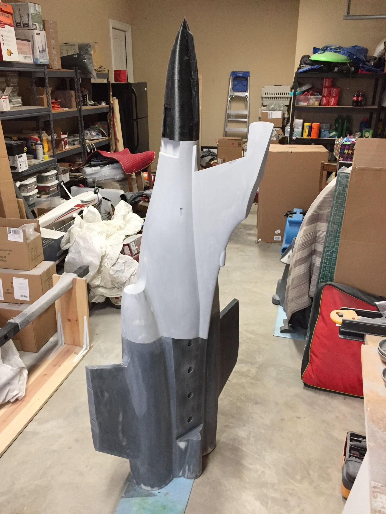
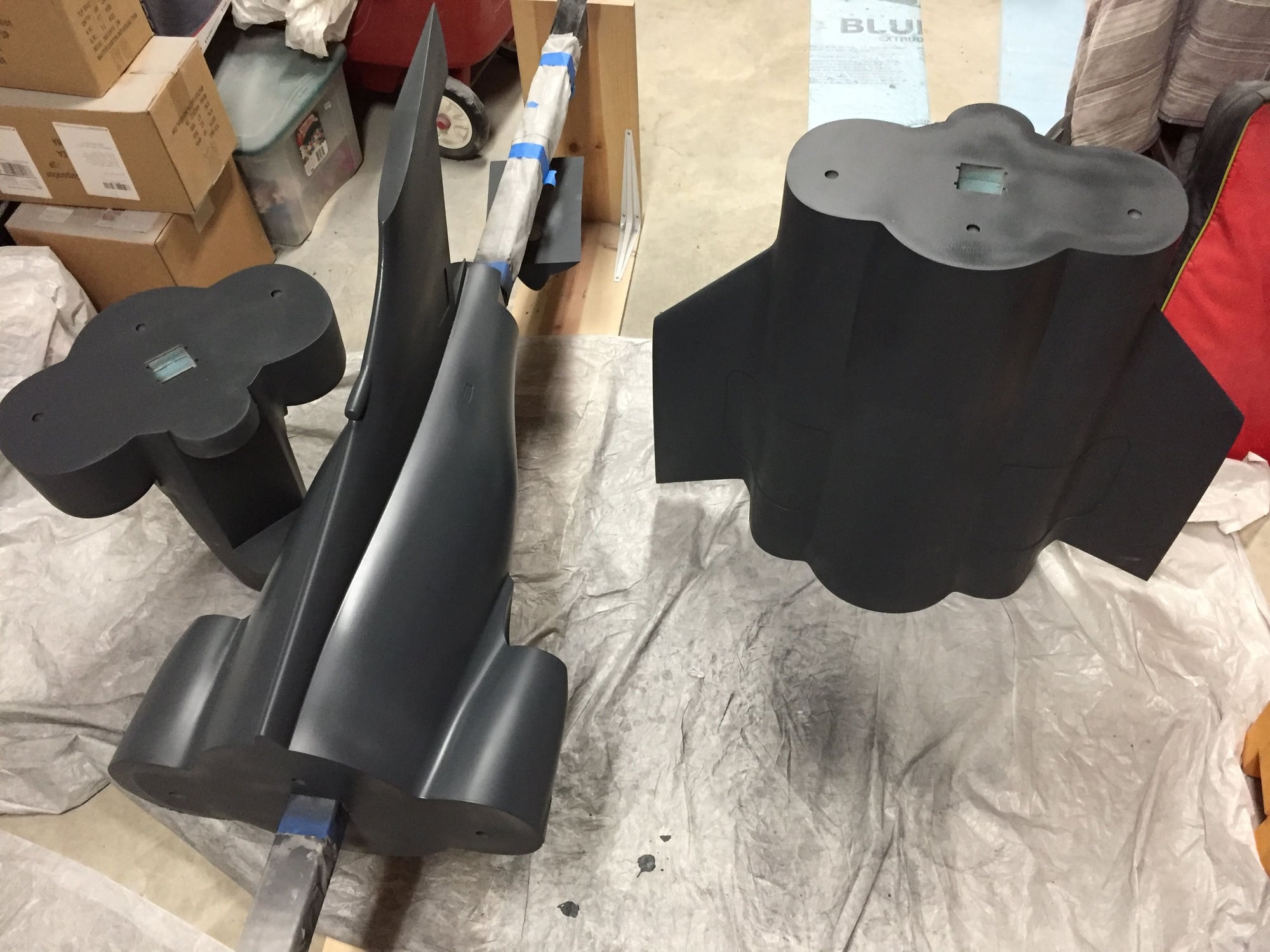
Finished printing the speedbrake plugs. These are monsters, 14.5" long. They certainly add an interesting element to the model.
I captured the external re-inforcement layer plus the internal surface detail with the lightening hole recesses.
Both are now ready for Duratec priming and detailing.
Paul
I captured the external re-inforcement layer plus the internal surface detail with the lightening hole recesses.
Both are now ready for Duratec priming and detailing.
Paul
12-30-2018, 01:37 PM
#154
Applied the second coat of basic primer to the rear fuselage section and rubbed down. Now ready for the Duratec primer.
Further painting on hold waiting on a new order of Duratec, as I had to throw away a brand new, un-opened gallon of it that I bought back in June. It had gone off and solidified. I complained to Fibreglast, but I was 3 weeks outside of their 6 month warranty period. Waiting on a call-back from their Manager, so hopefully I can get some credit for a wasted gallon.
Paul
 01-04-2019, 03:37 AM
#158
Join Date: Sep 2013
Posts: 631
Likes: 0
Received 0 Likes
on
0 Posts
01-04-2019, 04:25 AM
#159
Good question which I have thought about, but will look again. The concave undercut on the fairing just behind the exhaust is a risk for trapping the mold, but I was thinking that with the fin area and rear section released, the front part of the mold would release to the rear as all the curves taper that way. It does rely on a slightly flexible mold though, which isn't a great idea.
More thinking to do - thanks for the comments.
Paul
01-04-2019, 07:01 AM
#160
Either separate engine pods or a silicon insert that will flex out would be required from what I see. Were you moulding the fuselage in sections and joining too? It will add weight and make consistency and stability in the surface contour harder?
That fuselage is a complicated moulding!
That fuselage is a complicated moulding!
01-04-2019, 07:48 AM
#161
Just for ease of molding and fitting out, I was planning on having the fuselage split into 3 pieces just like the plug, and then bolting together (just like my DerJet Hunter).
I think it would be possible in the future to make a single piece fuselage using the same molds, as long as I get the molds bolted together accurately.
I think it would be possible in the future to make a single piece fuselage using the same molds, as long as I get the molds bolted together accurately.
01-04-2019, 11:03 AM
#163

I doubt. It looks like the release angles in that direction are too shallow. The mold is funneled by the engine pod.
 01-04-2019, 01:38 PM
#165

I just can't believe how much work this saves, being able to design the parting planes in cad and not have to trace them out and cut and fit and trim and scrap and redo....
Also on that area that looks like it might trap the mold, you can lay in a slug of silicone rubber and form a bit of a glove mold, but just over that one area.
Also on that area that looks like it might trap the mold, you can lay in a slug of silicone rubber and form a bit of a glove mold, but just over that one area.
01-04-2019, 07:10 PM
#166
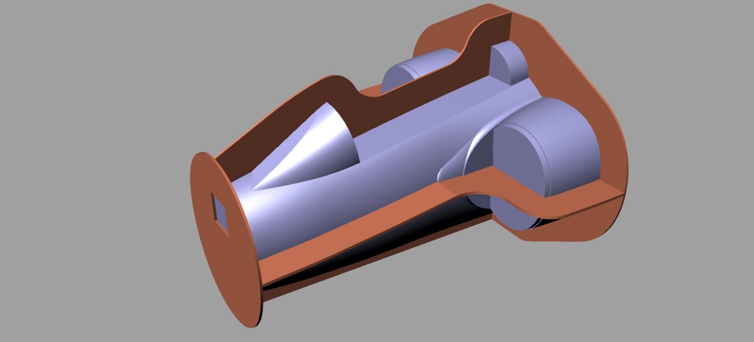
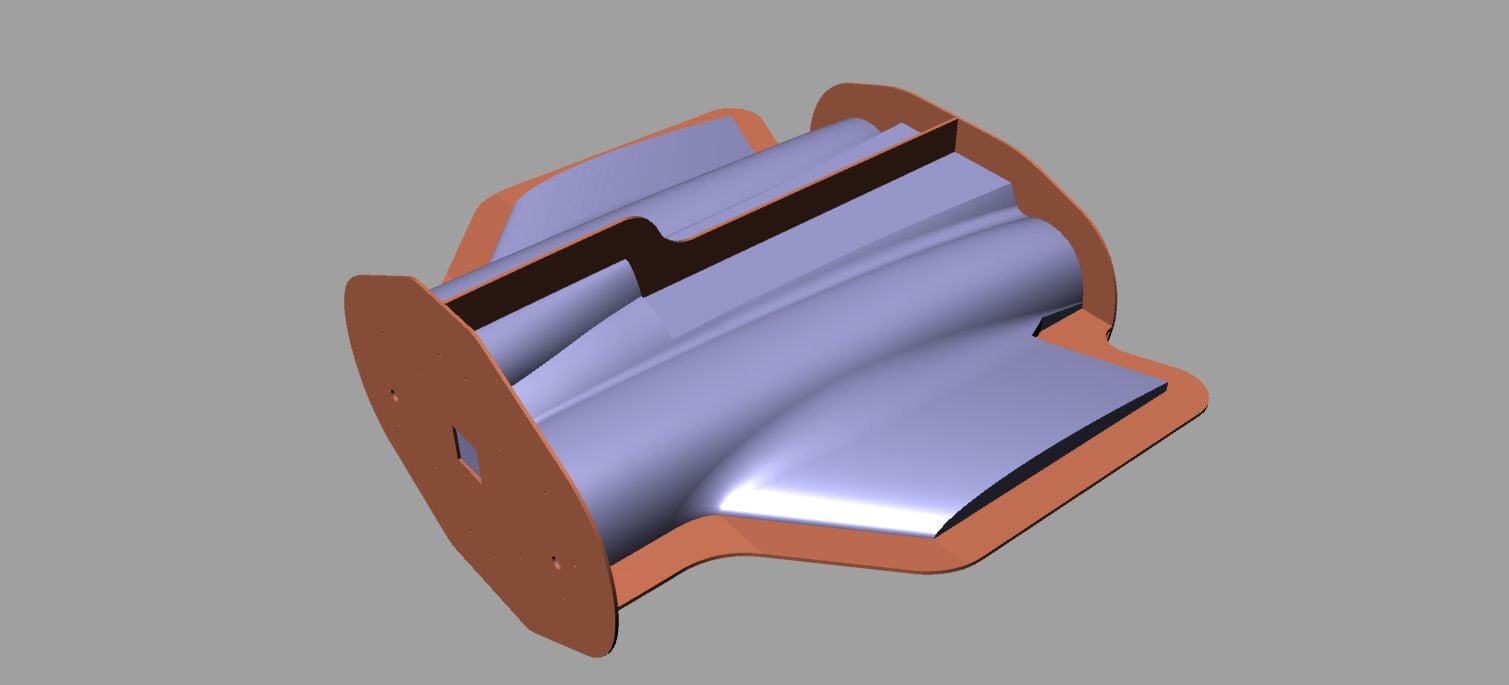
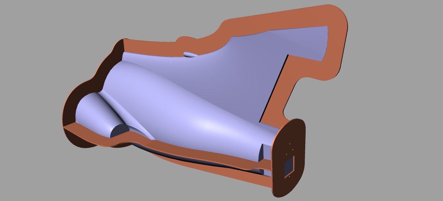
Updated rear fuselage parting planes to overcome the potential for trapped parts due to the negative draft angles. What a great resource RCU is with all the help and comments.
I may be able to make the forward bottom mold section in one piece, so it would be a 7 piece mold, otherwise it will be in 8 pieces.
My current thinking is to make the flight rear fuselage in 3 pieces, upper left, upper right and a lower half, and then assemble with the internal structure into a single part.
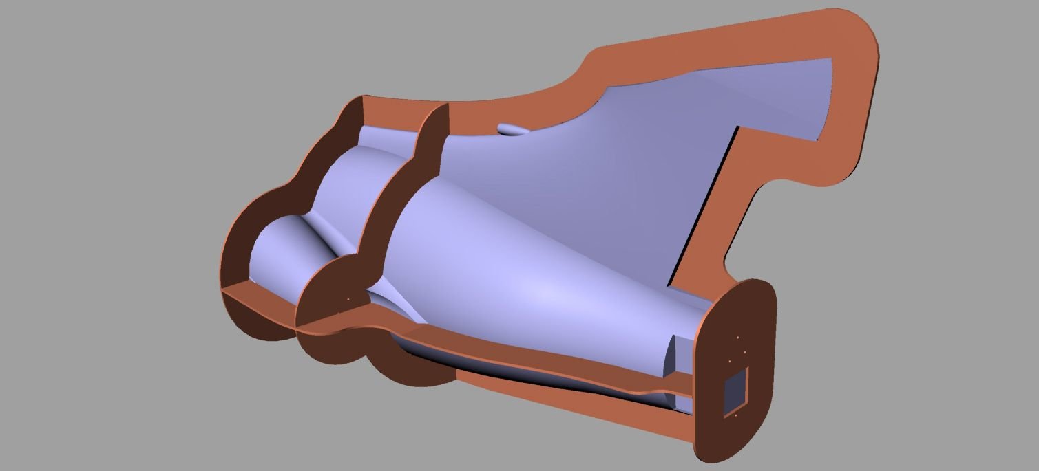
The arrows below show the intended mold removal directions, notionally perpendicular to the surface.
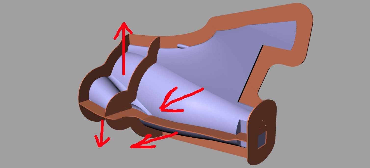
Paul
I may be able to make the forward bottom mold section in one piece, so it would be a 7 piece mold, otherwise it will be in 8 pieces.
My current thinking is to make the flight rear fuselage in 3 pieces, upper left, upper right and a lower half, and then assemble with the internal structure into a single part.
The arrows below show the intended mold removal directions, notionally perpendicular to the surface.
Paul
01-05-2019, 12:25 AM
#167
Paul
i don’t want to keep being the bad guy, what you have done is just amazing. This rear section is going to be critical on weight, anything extra back there is going to need nose weight added, each section you join will need tape and filling. It’s also lots of moulds.
i would cut off the turbine ducts, then you could make two half moulds for the whole fin/ rear fuselage, the pods then require two split moulds to produce each side. You may even be able to make them a removable section on key ways and pegs if you do end up with the turbines back there.
Dave
01-05-2019, 08:58 AM
#168

Updated rear fuselage parting planes to overcome the potential for trapped parts due to the negative draft angles. What a great resource RCU is with all the help and comments.
I may be able to make the forward bottom mold section in one piece, so it would be a 7 piece mold, otherwise it will be in 8 pieces.
My current thinking is to make the flight rear fuselage in 3 pieces, upper left, upper right and a lower half, and then assemble with the internal structure into a single part.
The arrows below show the intended mold removal directions, notionally perpendicular to the surface.
Paul
paul,
looks much better to me!
im assuming you would assemble the top Left and Right pair of molds (the sections with the V. Stab and engine exhausg undercut) as a single layup?
01-05-2019, 10:14 AM
#169
Paul
01-05-2019, 10:27 AM
#170
Paul
i don�t want to keep being the bad guy, what you have done is just amazing. This rear section is going to be critical on weight, anything extra back there is going to need nose weight added, each section you join will need tape and filling. It�s also lots of moulds.
i would cut off the turbine ducts, then you could make two half moulds for the whole fin/ rear fuselage, the pods then require two split moulds to produce each side. You may even be able to make them a removable section on key ways and pegs if you do end up with the turbines back there.
Dave
Appreciate the feedback.
At this point I think I have settled on a forward mounted engine configuration, but with the engines slightly inboard so that there is only one bend in each pipe, a long way back from the engine, similar to the DerJet Prowler solution, so that will help with the concern over being tail-heavy with the engines behind the c.g.
I don't think I could face cutting off the engine pods at this point - too much invested in the plugs. Not sure it would really save too much weight either compared with a single piece rear section, albeit composed of 3 or 4 separate moldings. It is only the molds that will be in 7 or 8 pieces, the actual flight parts will be laid up across multiple molds at once.
Paul
01-05-2019, 02:00 PM
#171
Join Date: Sep 2005
Location: LondonSurrey, UNITED KINGDOM
Posts: 396
Likes: 0
Received 0 Likes
on
0 Posts
Wet lay up and join would not require joining tape or glue and would not increase weight!
It’s a bit tedious doing an overlapped wet joints but it does mean you have a continuous moulding, this insures strength without gaining weight!
Downside: You have to work quite fast depending on the resin you use!
It’s a bit tedious doing an overlapped wet joints but it does mean you have a continuous moulding, this insures strength without gaining weight!
Downside: You have to work quite fast depending on the resin you use!
01-05-2019, 06:01 PM
#172
I was thinking that I would do the upper left and upper right as separate layups, then combine with the internal structure (fin spar etc.) and close it up with the lower half, and lay tape over the join line from the inside. Getting down into the narrow fin area as a single layup seems too difficult, especially when vacuum bagging too.
Paul
Paul
sorry, i should of been more clear. I meant doing each pair of Upper left molds and each pair of upper right mold layups separately. (Ie the upper left 2 molds would be �assembled� and then its layup done, then the same for the right. Afterwards the left/right molds halves would be joined with the structure).
01-11-2019, 04:43 PM
#174
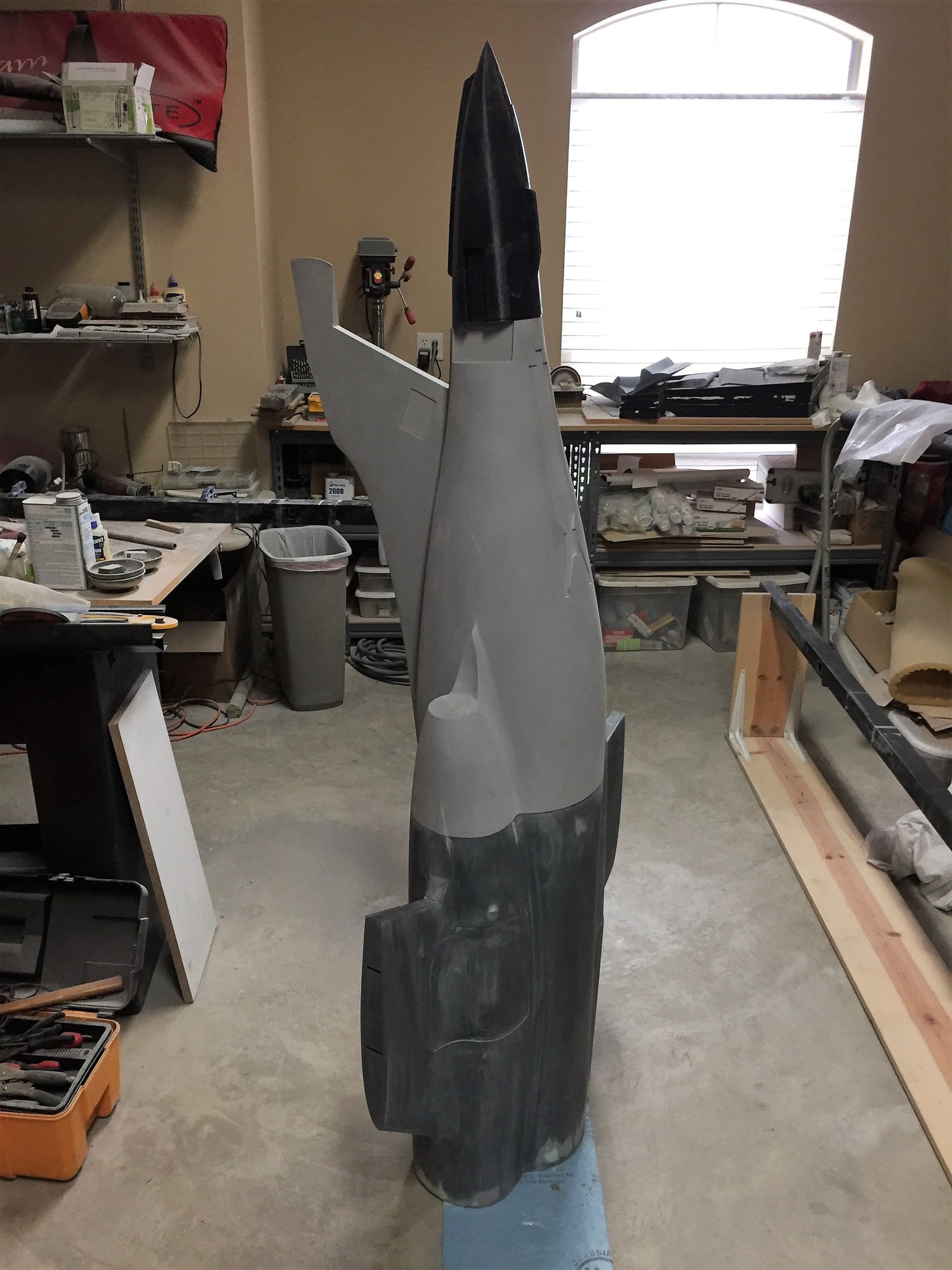
Finally got a delivery of more Duratec and sprayed all 3 major parts of the fuselage; final coats on the forward and center parts and an initial coat on the rear section.
Happy with the forward windshield profile on the third attempt, thanks to the photo from Dave.
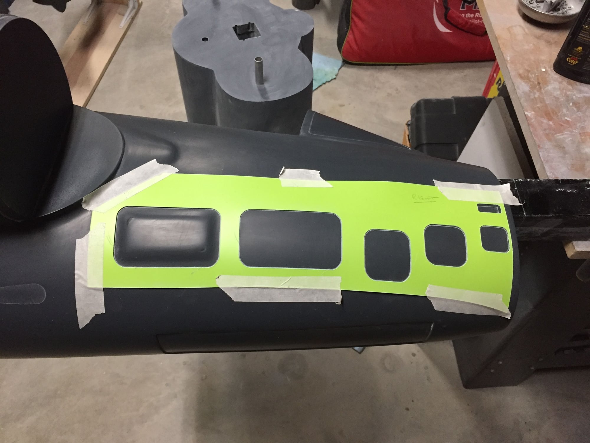
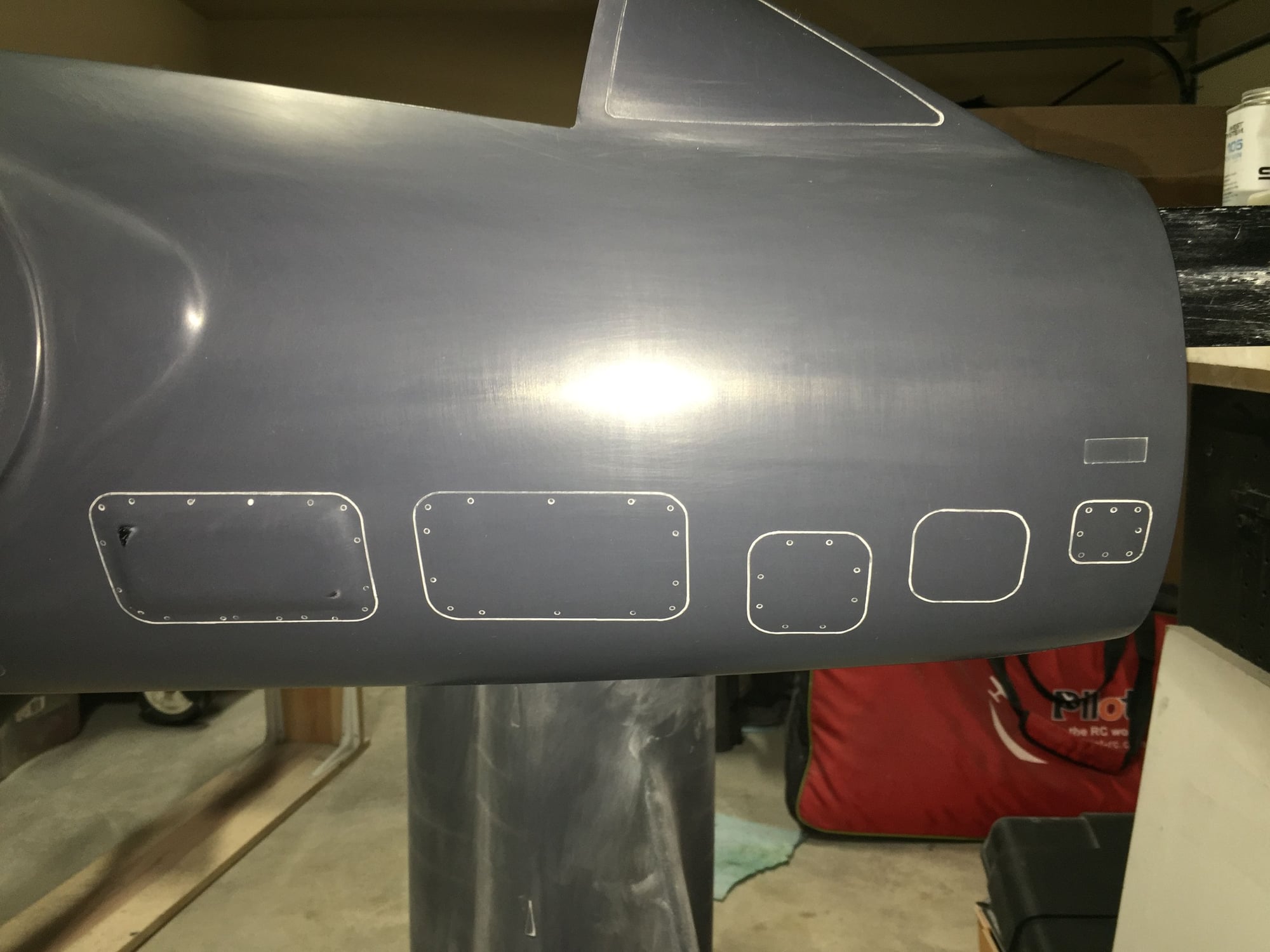
Have rubbed down the forward section and started to add surface detail to bring it to life. Scribing stencil for panel lines laser cut from plastic sign material from Lowes. Plenty more detail to add.
A couple of scribing errors to cover up and re-do. I'm sure there will be more.
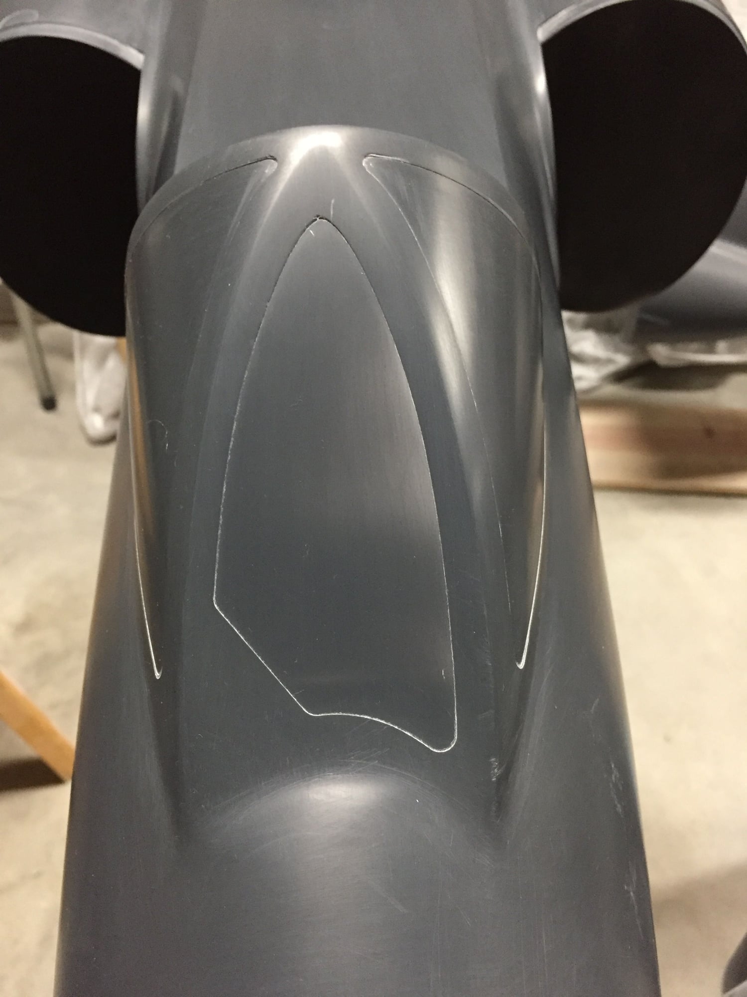
Paul
Happy with the forward windshield profile on the third attempt, thanks to the photo from Dave.
Have rubbed down the forward section and started to add surface detail to bring it to life. Scribing stencil for panel lines laser cut from plastic sign material from Lowes. Plenty more detail to add.
A couple of scribing errors to cover up and re-do. I'm sure there will be more.
Paul
Last edited by JSF-TC; 01-11-2019 at 04:46 PM.
01-13-2019, 08:12 PM
#175
Have been sanding on the center fuselage and hatches, so not much visible progress.
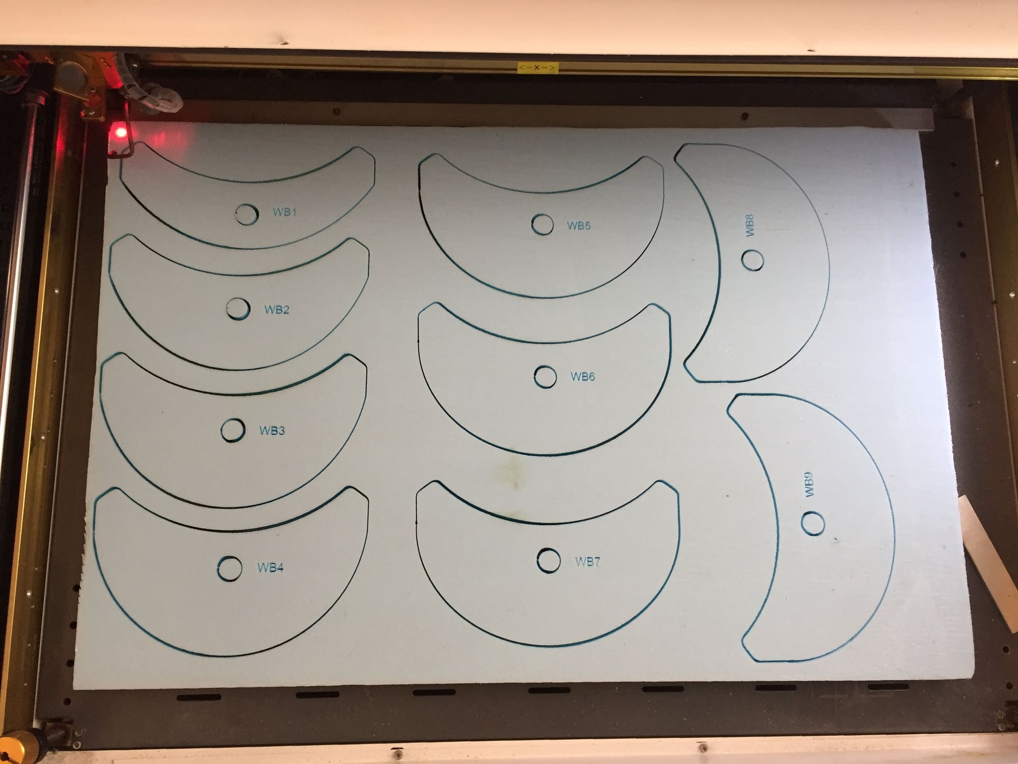
I have also started on the plug for the bulged weapons bay. Scale internal and external lines. Same construction as all the rest of the plug; ply and blue foam with 3D printed front and rear sections. It's large, over 30inches long. Will not likely use all of it for fuel, but my plan is for it to be rotating as per the full-scale.
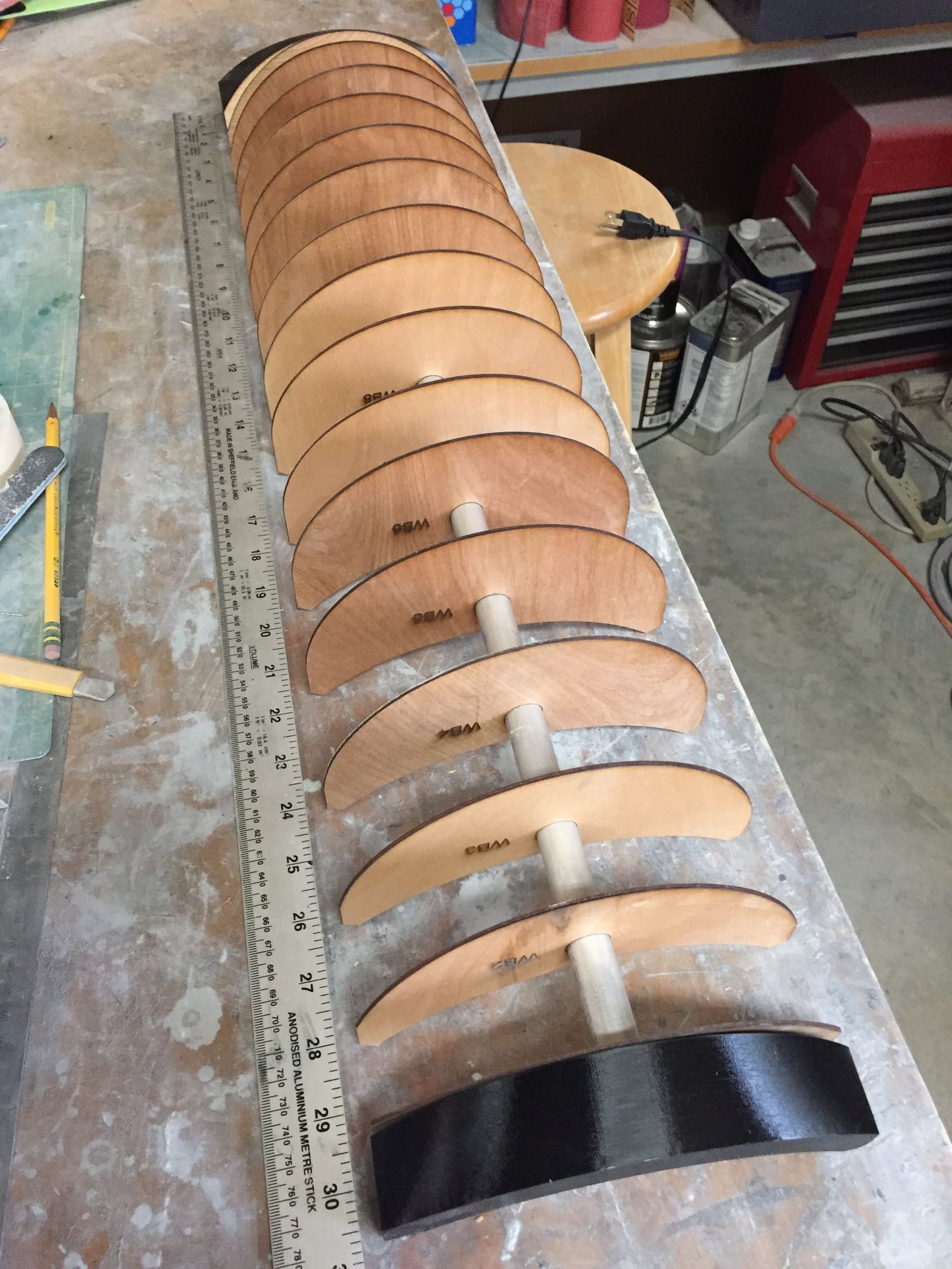
Laser cutting the blue foam filler sections for the plug.
Paul
I have also started on the plug for the bulged weapons bay. Scale internal and external lines. Same construction as all the rest of the plug; ply and blue foam with 3D printed front and rear sections. It's large, over 30inches long. Will not likely use all of it for fuel, but my plan is for it to be rotating as per the full-scale.
Laser cutting the blue foam filler sections for the plug.
Paul
Last edited by JSF-TC; 01-13-2019 at 08:16 PM.