


1/7 Scale Blackburn Buccaneer All Composite Scratch Build
 02-09-2021, 05:42 AM
#626

Join Date: Jan 2004
Location: Auckland, NEW ZEALAND
Posts: 24
Likes: 0
Received 0 Likes
on
0 Posts
Whilst not a jet guy, I have played quite a bit with high speed sailplanes including T tails. I'm curious about the pic a few posts above of the elevator servo and mount. I'm very surprised that on all other surfaces you have short direct pushrods, yet on the elevator you must have a pushrod about a foot long? I'm wondering if the possibility of it flexing is being considered and why not mount the elevator servo as close to the surface as possible near the top of the fin?
 02-09-2021, 09:25 AM
#628
Junior Member
The full-scale used high-pressure air for surface blowing on the wing leading edge, trailing edge flaps and tailplane leading edge to increase lift at slow speeds. I have read that the full-scale had issues if the blow was lost with the full flap deflections - I recall that running out of tailplane authority was the first major issue. I am not running the same flap deflections as full scale in part to avoid this issue, but maybe I need to reduce the full flap travel even more.
Paul
In the absence of those books that I used to have, I did a little searching around online and found some accounts from Bucc pilots in which they discuss unblown landings and takeoffs. I can't post the link here (RCU requires me to have 10 posts to my name before I can post a link, and my many thousands of prior posts were on an account I no longer have access to) - but if you search around on the PRPrune forums (maybe just add the start of their URL to: aviation-history-nostalgia/619039-buccaneer-blc.html ) you might see a discussion that included a post by user Lomcevak:
On the approach, datum speed for a given weight was 19 kts faster unblown with 45-10-10 than blown with 45-25-25. The problem blown was that if you throttled back even to minimum blow pressure (20 psi) you would have a very high rate of descent if you stabilised, and if you were fast and wanted to slow down you had to respect this minimum blow pressure. Also, you did not have sufficient thrust for a single engine approach. You could fly blown 30-20-20 and this was only 3 kts faster than 45-25-25 and you did have a single engine capability, albeit with relatively poor go-around capability. Therefore, if single engine the preference was to fly a 45-10-10 approach. Another relatively obscure case (and it did happen) was that if the airbrakes failed to open using the normal selector you either had to use the standby selector, which put the hydraulic system into emergency generating a lot more problems, or fly a 45-10-10 approach with the airbrakes closed because to fly the correct datum speed you could not use sufficient power to maintain the blow pressure if 45-25-25 or 30-20-20 without the airbrakes being open.
If you had a double generator failure you lost the 'cheeses' and so had to approach 45-0-0 which was 10 kts faster than 45-10-10; we did practise this and it was not difficult to fly, just fast (but then a Tornado in 67 wing approached at around 220-230 kts!). On my first landing at Gibraltar I had a 'cheese' failure and ended up 45-8-8. This concentrated the mind and, with maximum braking, I stopped in about half the runway length (ie. 3000 ft) so there was no real drama.
If I am understanding the above quote correctly, then it looks like the unblown approach simply reduced the droop and tailplane flap components rather than reducing the (primary) flap setting.
Regards,
Gordon
Last edited by Gordon_Mc; 02-09-2021 at 09:26 AM. Reason: Emphasize which info is a quote
02-09-2021, 09:47 AM
#629


David,
That is incorrect - the primary pitch control is an all-moving tailplane. The small tailplane trailing edge flaps only deflect (up) as a flap when the wing flaps deploy (down) to act as a trim device. The trailing edge flaps do not respond to pitch control inputs.
Paul
That is incorrect - the primary pitch control is an all-moving tailplane. The small tailplane trailing edge flaps only deflect (up) as a flap when the wing flaps deploy (down) to act as a trim device. The trailing edge flaps do not respond to pitch control inputs.
Paul
On most aircraft, the all moving tailplane is a trimmer and the elevators are the primary pitch control unit.
Given the size of the elevators, I would strongly suggest you to use them as your primary pitch control devices and make your all moving tailplane a pitch trimmer.
Nevertheless, I doubt your elevators would be able to over-power your staibilizer. However I can compute this precisely with Ansys if you wish to.
By the way, I cannot open you log file neither, under Jeti Studio. However I can see the csv entries in a text editor.
You telemetry setup is missing some essential data: you need to record your stick positions.
Also I would recommend you to install a pitot tube and a GPS.
That way you will be able to spot your speed at a given position in your pattern and check your antennae diagram give the airplane orientation.
TAS feedback is quite essential for test flying an aircraft.
Last edited by olnico; 02-09-2021 at 09:54 AM.
02-09-2021, 09:52 AM
#630
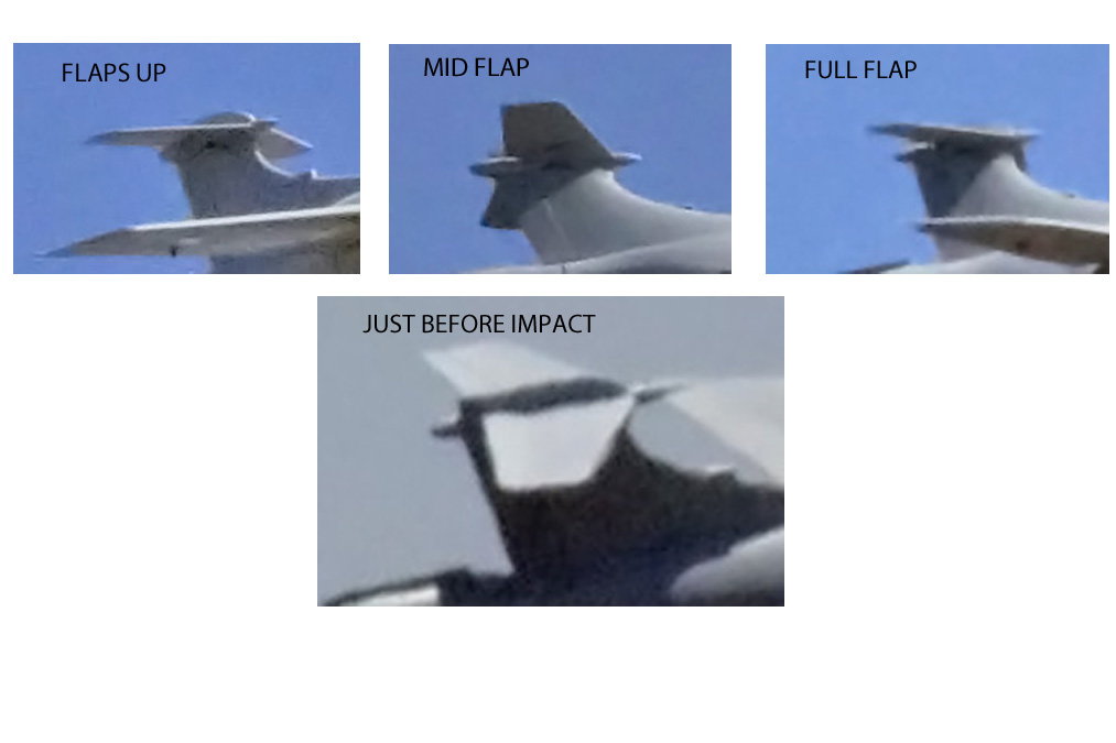
The last picture shows a full up elevator and a flat stabilizer. Doesn't it?
Would you be able to confirm your stabilizer deflection from the angle of the top fairing to the rear fairing?
02-09-2021, 10:32 AM
#631

Gordon,
Welcome back and thanks for watching and your comments. I loved your Hunter and Jaguar builds back in the day. Yes, I have that same PPRune info saved off for reference.
Over on RCScaleBuilder, Andy Sephton, a UK Test Pilot posted the following, which may be of interest.
Paul
Welcome back and thanks for watching and your comments. I loved your Hunter and Jaguar builds back in the day. Yes, I have that same PPRune info saved off for reference.
Over on RCScaleBuilder, Andy Sephton, a UK Test Pilot posted the following, which may be of interest.
I was fortunate (?) enough to fly the Buccaneer as a Test Pilot in the RAF. It was a potent aircraft, but it did have some interesting aerodynamic characteristics around which grew a number of myths. I'll try to explain a few here:
- Yaw stability: in order to fit the aircraft into a carrier flight hangar, the fin height was limited. The fuselage was area ruled to reduce high subsonic drag, hence the shape. The two come together to give limited yaw stability at speed. This shouldn't affect a model, however.
- Roll/yaw coupling: The aircraft has a long heavy fuselage and relatively light wings. If rolled and pitched at the same time, the two can couple together to cause the aircraft to depart. The pilots got around this by rolling then pulling, never doing the two at the same time. Again, this shouldn't affect a model unless done to excess.
- Flaps: The aircraft had inboard flaps on the wings, outboard drooped ailerons and a flap at the rear of the all-moving tailplane to balance the aileron droop and flap. The normal settings were 15:10:10, 30:20:20, and 45:25:25, the figures being degrees deflection of the flap, aileron and tailplane flap respectively. The wing flap and ailerons deflected down the tailplane flap deflected up. An emergency setting was sometimes used when no bleed (see next bullet) was available of 45:10:10. The extreme flap settings were required to get the aircraft off the carrier deck and back on to it safely.
- Bleed: Boundary layer bleed was used to energise the boundary layer airflow over the wing and tailplane to keep the airflow attached. It came on automatically between 10 and 20 degrees deflection of the aileron droop and tailplane flap. Hence, if the bleed was unserviceable, the aileron droop and tailplane flap deflection was limited to 10 degrees. In practice the bleed was not really required at 20 degrees deflection, but it was essential at 25 degrees. 25 degrees was required to get the speed low enough for carrier operations, so the bleed was essential for carrier ops.
- Variable aileron deflection: There was a pilot operated lever in the cockpit to change the aileron gearing from high to low when accelerating though 300 knots, and vice versa. The limited aileron deflection was an aid to prevent roll/yaw coupling at higher speeds.
I realise that a lot of that is not really relevant to the operation of a model, I hope it helps to understand the design of the aircraft. Whilst it wasn't one of my favourites (the Harrier gets that ticket), it was a potent aircraft in its day and was much liked by its aircrews.
02-09-2021, 11:58 AM
#632
It dawned on me in the middle of the night how correct you were in that comment about the linkage geometry, and how wrong my initial response was, so I have struck part of my response through.
A more considered analysis.
If we assume that the LTMA calculations assume perfect 90deg linkage geometry, so that all the servo torque is available as an input to drive the control surface, then with the Buccaneer tailplane geometry, where the pushrod is set up so that it is at an angle of 19.35deg, I should have accounted for the loss in the effective control arm radius, which is shown below.
At the servo end, the geometry was set up with the pushrod at 90deg to the servo arm.
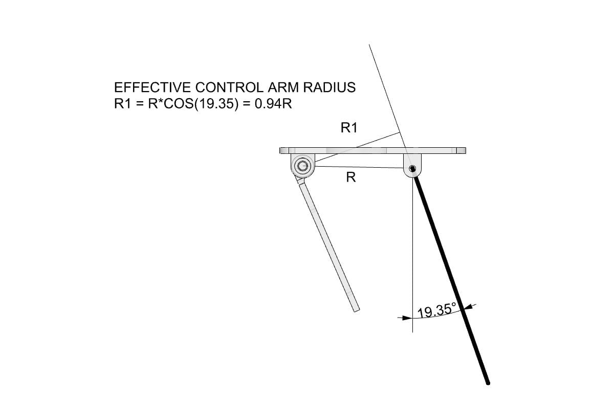
The basic LTMA calculation suggested a requirement of 306oz.in (using R for the control arm radius).
Correcting for the 'effective control arm radius - R1' would give a minimum torque requirement of 325oz.in.
I had used an MKS 777+ servo, with a torque of 506oz.in at 7.4V.
So, even accounting for the incorrect calculation of servo torque, the above suggests that I should still have had plenty of margin to the minimum requirements.
I feel better now for having worked through the geometry calculations. I still think that Tom's suggestion of the tailplane pitching moment with the trailing edge flap deflected helped overpower the servo is a primary cause, and with the resulting dive and increasing speed, the forces only got greater with no recovery possible. The only way out would have been to retract the flaps, which I initiated, but with the 10sec travel time there was not sufficient time before impact.
I think next time I will keep the tailplane trailing edge flaps on a separate knob and only start to investigate their effect once the basic model is understood, and not have them mixed in with the flaps from the very beginning.
Paul
A more considered analysis.
If we assume that the LTMA calculations assume perfect 90deg linkage geometry, so that all the servo torque is available as an input to drive the control surface, then with the Buccaneer tailplane geometry, where the pushrod is set up so that it is at an angle of 19.35deg, I should have accounted for the loss in the effective control arm radius, which is shown below.
At the servo end, the geometry was set up with the pushrod at 90deg to the servo arm.
The basic LTMA calculation suggested a requirement of 306oz.in (using R for the control arm radius).
Correcting for the 'effective control arm radius - R1' would give a minimum torque requirement of 325oz.in.
I had used an MKS 777+ servo, with a torque of 506oz.in at 7.4V.
So, even accounting for the incorrect calculation of servo torque, the above suggests that I should still have had plenty of margin to the minimum requirements.
I feel better now for having worked through the geometry calculations. I still think that Tom's suggestion of the tailplane pitching moment with the trailing edge flap deflected helped overpower the servo is a primary cause, and with the resulting dive and increasing speed, the forces only got greater with no recovery possible. The only way out would have been to retract the flaps, which I initiated, but with the 10sec travel time there was not sufficient time before impact.
I think next time I will keep the tailplane trailing edge flaps on a separate knob and only start to investigate their effect once the basic model is understood, and not have them mixed in with the flaps from the very beginning.
Paul
Paul
You are calculating at the neutral point, so holding power. Have you calculated it at full up? The leverage is reducing just when the load is greatest?
Dave
02-09-2021, 12:43 PM
#633
Dave,
Another great question. I should have had you do a design review before I flew it.
Slight correction to the neutral position calculation, but it didn't change the result.
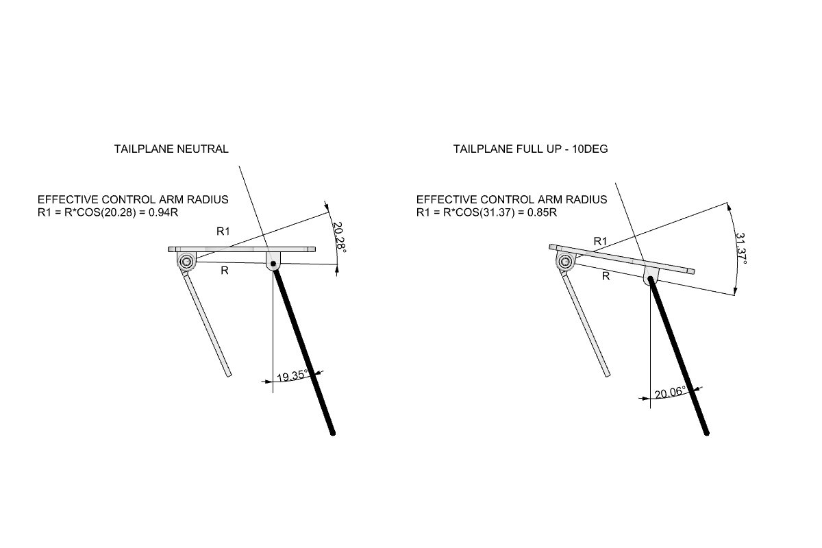
With full up (10deg), the effective radius reduces to 0.85R, driving up the required minimum servo torque to 360oz.in. Should still have been within the servo capabilities (506oz.in).
Keep the questions coming.
Paul
Another great question. I should have had you do a design review before I flew it.
Slight correction to the neutral position calculation, but it didn't change the result.
With full up (10deg), the effective radius reduces to 0.85R, driving up the required minimum servo torque to 360oz.in. Should still have been within the servo capabilities (506oz.in).
Keep the questions coming.
Paul
Last edited by JSF-TC; 02-09-2021 at 12:49 PM.
02-09-2021, 01:23 PM
#634
You are still quoting torque at 0-1cm arm radius on the servo? Also anyone actually tested a 777+ to see what torque it really produces? Most servos don’t match the ‘lab’ figures. I’m very much “ you cannot over power a control surface” if you were local to me for sure I would have steered you differently on many things! I’m also ‘phobic’ of the load on 1970’s servo spline sizing. I like the idea of MKS’s 8mm spline and think more manufacturers should follow. In your set up I would have recommended two servos, mirrored and probably two pushrods going up to remove all the single points of failure. I prefer two 20kg servos over one 40kg...
Dave
Dave
02-09-2021, 05:58 PM
#636
My Feedback: (2)

Join Date: May 2002
Location: Honolulu,
HI
Posts: 924
Likes: 0
Received 0 Likes
on
0 Posts
Hi Paul
Been watching you design and build this fantastic Jet, you work is very inspirational, and gave me something to look forward to during this so fun year, thank you for taking the time to share this!
Your constructive attitude after your setback is great, so great to see you moving forward with the project.
Many years ago when I had the first smaller Skymaster Hawk, I ran into a situation where during landing if you had full flaps and you went too fast on final it felt like you lost elevator control.
We found that only slowing down got you out of the situation, very disconcerting in real time.
Interesting that David Gladwin mentioned how the full scale had a similar issue that needed fixes. Its amazing how powerful the flap downwash effect is.
I also remember from full scale flight training the Piper PA-28 I flew had a small elevator trim tab but it was pretty powerful for trimming the stab.
Last edited by Aero65; 02-09-2021 at 06:10 PM.
02-09-2021, 10:08 PM
#637
Duke
The SM ‘semi scale’ first kit was almost certainly due to the reduced distance vertical separation between wing and tail. Reducing the flap angle to around 35 degrees made that manageable-also adding some CROW on the ailerons to change the wing profile.
The SM ‘semi scale’ first kit was almost certainly due to the reduced distance vertical separation between wing and tail. Reducing the flap angle to around 35 degrees made that manageable-also adding some CROW on the ailerons to change the wing profile.
02-10-2021, 10:10 AM
#638
My Feedback: (2)
Join Date: May 2002
Location: Honolulu,
HI
Posts: 924
Likes: 0
Received 0 Likes
on
0 Posts
Hello Dave
I did that to mine, it did really help. Before I changed the settings I experienced having the elevator go non responsive, it was not something I care to repeat.
Sorry it had to happen to the Paul and his Buccaneer, with all the great thinking and ideas on this thread sounds like it will get worked out.
02-17-2021, 11:21 AM
#642

Paul, Speaking of structures, ----
When I look at the photos on post #402 of your Buccaneer in its bare bones, in the absence of a wing tube, what carries the bending moment across the fuselage? What stops the wings from clapping above the pilot's head?
Say your loaded weight is 50 kg, and you pull 9g in a tight turn or loop, that's a fearsome bending moment in the centre. There must be more to the structure that those bits of laser-cut ply.
What did I miss?
Alasdair
02-17-2021, 11:38 AM
#643
Alasdair,
The empty weight is ~50lb, about 24kg. I'd be really worried if it came out at 50kg - I know I don't build light, but that would be heavy even for me! - but I get your point!.
What you see is it - the only parts missing are cross braces across the top of the center 'U' on each of the 3 major bulkheads.
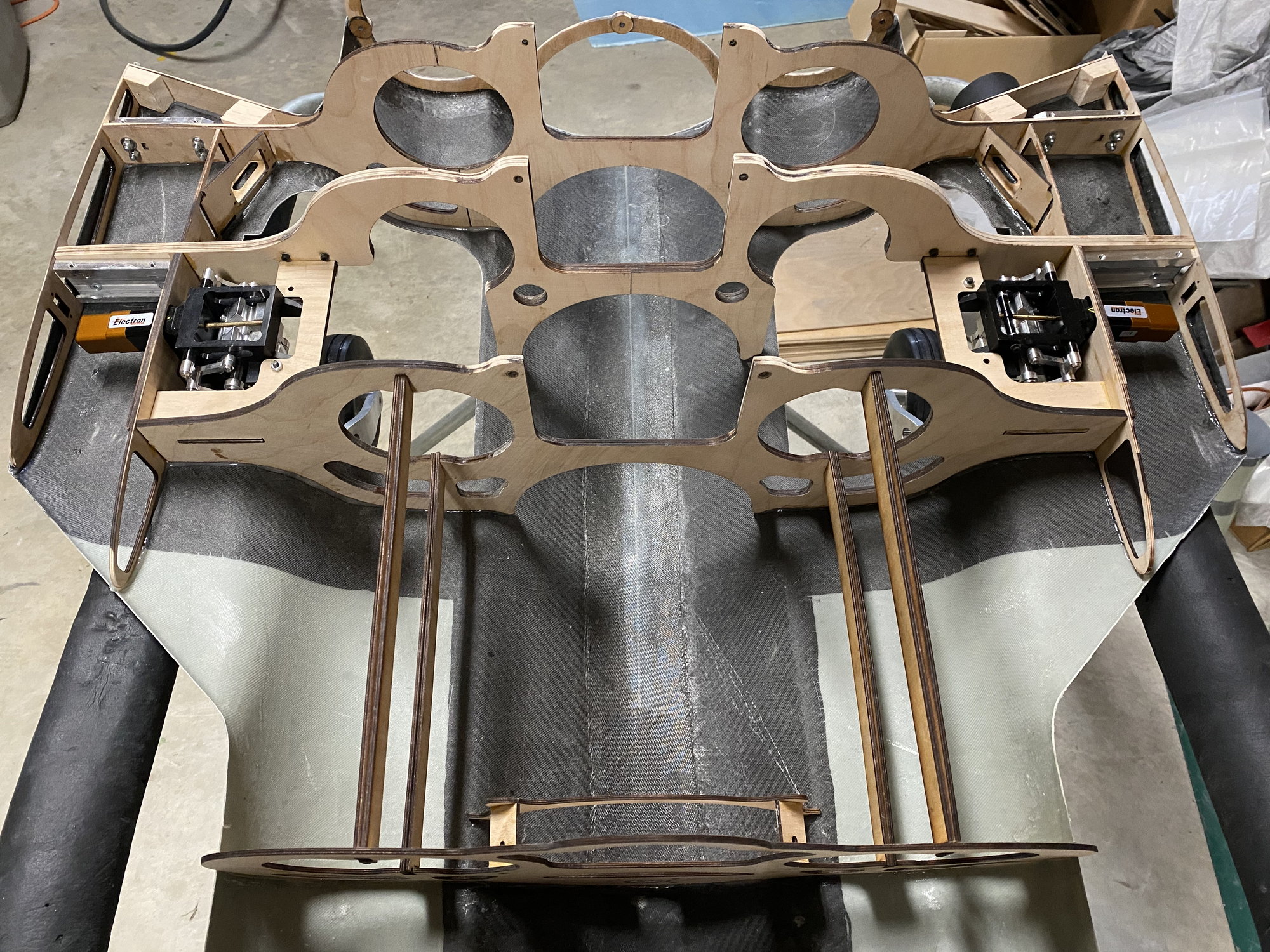
If you read back in the thread, you will see where I was concerned about the strength of the bulkhead that carries the forward wing joiner, because of its shape. The bottom half of the loop that goes around the thrust tube has to be cut away to allow the gear to retract, thereby removing the 'tension' path that results from normal wing bending under G.
To offset that loss of strength, that forward wing joiner bulkhead is made of 3 layers of 1/8" birch 5-ply, giving a thickness of 3/8". The rear bulkhead, which has a much better structural configuration is only 2 layers for 1/4" thickness.
The forward of the 3 bulkheads is also 2 layers of 1/8" as it carries the landing gear mounting plate and loads.
I don't plan on ever pulling 9G but your concern is valid. I think Dave believes that I've over-built it, but I'd rather have excess strength in that area.
Paul
The empty weight is ~50lb, about 24kg. I'd be really worried if it came out at 50kg - I know I don't build light, but that would be heavy even for me! - but I get your point!.
What you see is it - the only parts missing are cross braces across the top of the center 'U' on each of the 3 major bulkheads.
If you read back in the thread, you will see where I was concerned about the strength of the bulkhead that carries the forward wing joiner, because of its shape. The bottom half of the loop that goes around the thrust tube has to be cut away to allow the gear to retract, thereby removing the 'tension' path that results from normal wing bending under G.
To offset that loss of strength, that forward wing joiner bulkhead is made of 3 layers of 1/8" birch 5-ply, giving a thickness of 3/8". The rear bulkhead, which has a much better structural configuration is only 2 layers for 1/4" thickness.
The forward of the 3 bulkheads is also 2 layers of 1/8" as it carries the landing gear mounting plate and loads.
I don't plan on ever pulling 9G but your concern is valid. I think Dave believes that I've over-built it, but I'd rather have excess strength in that area.
Paul
02-17-2021, 12:03 PM
#644

In the text at the end of the movie, he points to the receiver voltage regulator, being undersized.
Lars
Lars
https://www.youtube.com/watch?v=627F...rkusNussbaumer
I saw this video on youtube today, not sure what causes the crash but it looks like the stabilizer/wing stalls and the airplane dives to the ground.
I saw this video on youtube today, not sure what causes the crash but it looks like the stabilizer/wing stalls and the airplane dives to the ground.
02-17-2021, 12:07 PM
#645
Hi Paul,
That was quick. Sorry about the weight gain. I had 50 in my mind, and the kg was added without checking back -- it's such a long thread. I had also imagined double your thrust at a pair of 200N engines instead of 100s, so it seemed fair.
I once fitted a set of Eagletree data recording systems to my O/D Jet trainer (JayTee see my avatar).
Top speed was a modest 125 mph, stall 23 mph and in a series of ever-tighter loops I recorded 9g positive and 9g negative. I wasn't trying to break it, just exploring the envelope. So now I regard 9g as my easily reached limit. It might have been that flight when I bent my wing tube. Or, the scary option, maybe not.
I suppose I do tend to over-build things. I've never had one come apart in flight.
If Dave thinks it's strong enough then I bow to his vastly greater experience.
02-17-2021, 12:44 PM
#647
Hi Alasdair,
Similarly, I built a DIY accelerometer for my Jeti (from the RCThoughts design) and installed it in my Ultra Flash. I have it set to announce when the maximum I pull is over 6G. It announces the maximum once I have relaxed below 6G (these values are user adjustable in the LUA based menu)
I can fly a whole flight without triggering the 6G announcements and to get 9G feels slightly aggressive to me, but easy to do at 200mph. I did do what you did by flying ever tighter turns and I got to 12G before it flicked out. The accelerometer max's out at 16G and I have never got close.
I tend to fly my scale jets a lot smoother than the Ultra Flash, so probably 4-5G max would be my expectation. Above that I've done something wrong.
I didn't try to do any sort of stress calcs on the Buccaneer design apart from TLAR (That Looks Auout Right).
Paul
02-17-2021, 01:14 PM
#648
Look at the DerJet Vampire ( there are other aircraft done the same way) that has blade spars bolted to loop formers. These formers take the bending load, unsupported plywood would buckle and fail, but sandwiched between the two skins they become an I beam. Paul�s carbon placement is perfect,
I used to have competitions with my father to make balsa wood bridges and load them. Lightest bridge and greatest load...it teaches you so much watching the structure start to bow and flex before failure. You learnt to brace the bits that required and lighten parts that showed no duress.
I had an electric model design published back in the 80�s and a well known designer here David Boddington was the magazine editor, he had seen the model flown and asked for a plan. When I delivered the plan he rolled it out and just smiled at me saying not much plywood in there. It used a 6 cell Nicad and brushed 540 can motor and had less than 2� of 1/16� plywood in the whole design! I said I design my models to be strong enough to fly-not strong enough to crash! He laughed and said �great�. He knew a thing or two...his full scale BE2 replica is still flying today.
Dave
02-17-2021, 03:15 PM
#649
I was thinking more linkage/hinge failure.
Look at the DerJet Vampire ( there are other aircraft done the same way) that has blade spars bolted to loop formers. These formers take the bending load, unsupported plywood would buckle and fail, but sandwiched between the two skins they become an I beam. Paul�s carbon placement is perfect,
I used to have competitions with my father to make balsa wood bridges and load them. Lightest bridge and greatest load...it teaches you so much watching the structure start to bow and flex before failure. You learnt to brace the bits that required and lighten parts that showed no duress.
I had an electric model design published back in the 80�s and a well known designer here David Boddington was the magazine editor, he had seen the model flown and asked for a plan. When I delivered the plan he rolled it out and just smiled at me saying not much plywood in there. It used a 6 cell Nicad and brushed 540 can motor and had less than 2� of 1/16� plywood in the whole design! I said I design my models to be strong enough to fly-not strong enough to crash! He laughed and said �great�. He knew a thing or two...his full scale BE2 replica is still flying today.
Dave