


1/7 Scale Blackburn Buccaneer All Composite Scratch Build
 01-19-2021, 07:36 AM
#576

I had used the laminating resin, thickened with silica, to make a thixotropic paste for bonding in the internal structure, using the assumption that the same resin as used for the laminate would avoid any incompatibility issues and form a good bond.
Apparently, laminating resin is not intended to be an adhesive,
Paul
 01-31-2021, 02:26 PM
#578

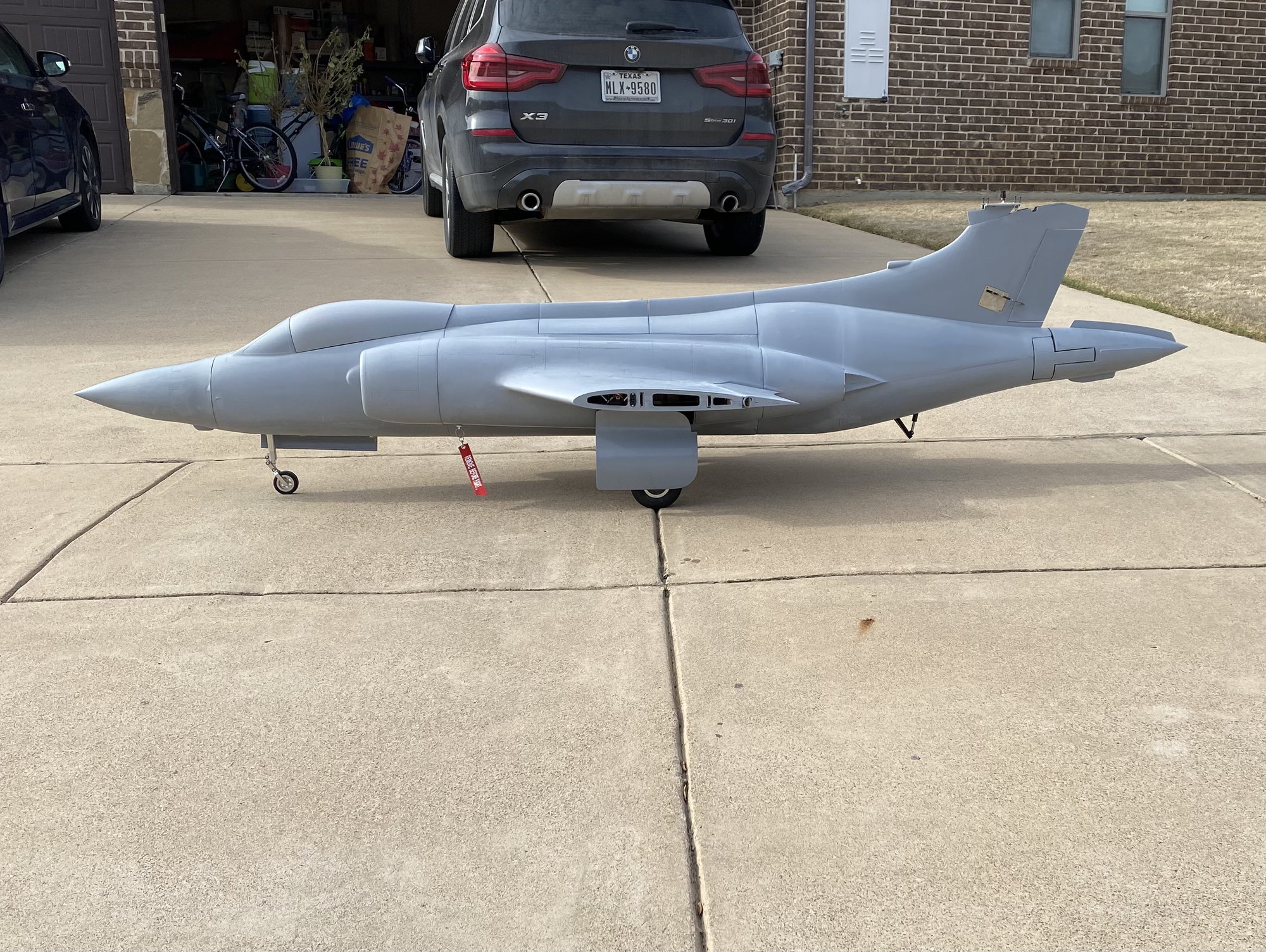
The Buccaneer is fully repaired and ready to try again.
All the fuselage frames had a 1" glass cloth lap joint applied to them to reinforce all the joints. There was only a couple of glass skin cracks that were easily fixed with a glass cloth patch on the inside. The broken main gear mounting plates and supporting ribs were the hardest to replace, but luckily they were fully accessible and new parts could be inserted and bonded into place without too much difficulty.
On re-assembly, the repairs cost slightly over 1/2lb in weight, but I think it was well worth it.
With the raised nose gear mounting position, shorter strut and smaller nose wheel, the ground attitude is now correct - it now sits perfectly level, whereas before it had a 2-3deg nose up sit.
I also added about 1lb of nose ballast to pull the c.g. forward. Based on the 'finger-tip balance along the leading edge' technique this showed the c.g. to be around the forward c.g. limit based on the full-scale data. Using the Xicoy balance, this indicated the c.g. to be a little further aft of that, but forward of the mid-point of the full-scale c.g. range. I now have an additional 1.5lb of weight on the nose gear and it feels more solid.
When I fully compress the nose gear and release it I now only get about a 1" nose wheel bounce. While I didn't to the compressed nose gear test previously I fully expect it would have shown a significant bounce/ pitch-up, which would have exacerbated the big pitch up seen on the taxy test.
I found an on-line model c.g. calculator, https://rcplanes.online/cg2_calc.htm and I ran the Buccaneer geometry through it. It predicted that my original c.g. position resulted in an apoprox 3% static margin. It recommends a 5-15% static margin for a model, less being less stable/ more responsive.
As a double check/ calibration of these values, I also calculated the c.g. position for my DerJet Hunter which I have been flying for the past 5 years. It is a very stable and smooth flying model, albeit it was almost lost on the early flights due to the c.g. being too far after resulting in pitch up & departure tendencies. I was expecting a large Static Margin based on how it currently flies, but the calculator suggested that where I currently have it balanced results in a 5% static margin.
Where the Buccaneer is currently balanced with the additional ballast it is predicted to be around an 6% static margin. I feel comfortable with this as a starting point, especially given how the Hunter flies. I can always progressively remove this ballast to fine tune the balance point.
Now just waiting for better weather.
Paul
01-31-2021, 03:15 PM
#579

My Feedback: (20)
Paul,
Great work. What an awesome project! Look forward to seeing next tests.
Great find on the CG calculator. I've bookmarked it for use on my F-105 when the time comes. Hopefully it will validate the info I have from the previous flight tests of the few that have flown.
Thanks again for all the help you gave me.
Gary
02-01-2021, 03:20 AM
#580
Hello Paul,
I am one of many following your project.
Very nice 'turn-around' on the build. Like others, I look forward to your continued success with the Buccaneer.
Frank
I am one of many following your project.
Very nice 'turn-around' on the build. Like others, I look forward to your continued success with the Buccaneer.
Frank
02-01-2021, 04:56 AM
#581
Gary, Frank,
Thanks for the comments and continued support. I'm feeling good about the real first flight. Hopefully next weekend, weather permitting.
Gary, your 105 project is looking great, and Frank's Draken is beautiful. All very unique projects.
Paul
Thanks for the comments and continued support. I'm feeling good about the real first flight. Hopefully next weekend, weather permitting.
Gary, your 105 project is looking great, and Frank's Draken is beautiful. All very unique projects.
Paul
The following users liked this post:
TheEdge (02-01-2021)

The following users liked this post:
u2fast (02-03-2021)
02-07-2021, 05:10 PM
#584
Well, today was the day. Weather was perfect if a little cool to start with. Wind was about 10mph straight down the runway.
I completed engine off and engine running range checks, taxi steering check plus a Jeti Assist gyro check as there have been plenty of reports of the Jeti Assist gyro suffering from acoustic pickup causing jittering surfaces. No issue at idle and low power, but jittering was apparent on all surfaces at high power. Turning the gain down to zero stopped the jittering. I reasoned that I would keep the gyro active with gain to zero, so that I could activate the gyro if needed, reasoning that if I needed the gyro to smooth out the model, that was more critical than the small possibility of the high frequency jittering causing issues at the slow speeds of the first flight. But something to fix for future flights.
The initial take off was done flaps up. The take off was great - tracked straight and the rotation was smooth with a positive climb away. Roll was very sensitive due to the full-span ailerons, even with 60% rates and 20% expo, so I induced a couple of roll oscillations until I got in sync with it. Some minor trimming in pitch and roll was needed to get it flying hands off.
Keeping the gear down for the entire flight, I reduced power to about 50% midway on downwind and it settled into a comfortable speed. I flew a couple of laps getting the feel for it, adjusting my gains to accommodate the sensitive ailerons and to fine tune the trims.
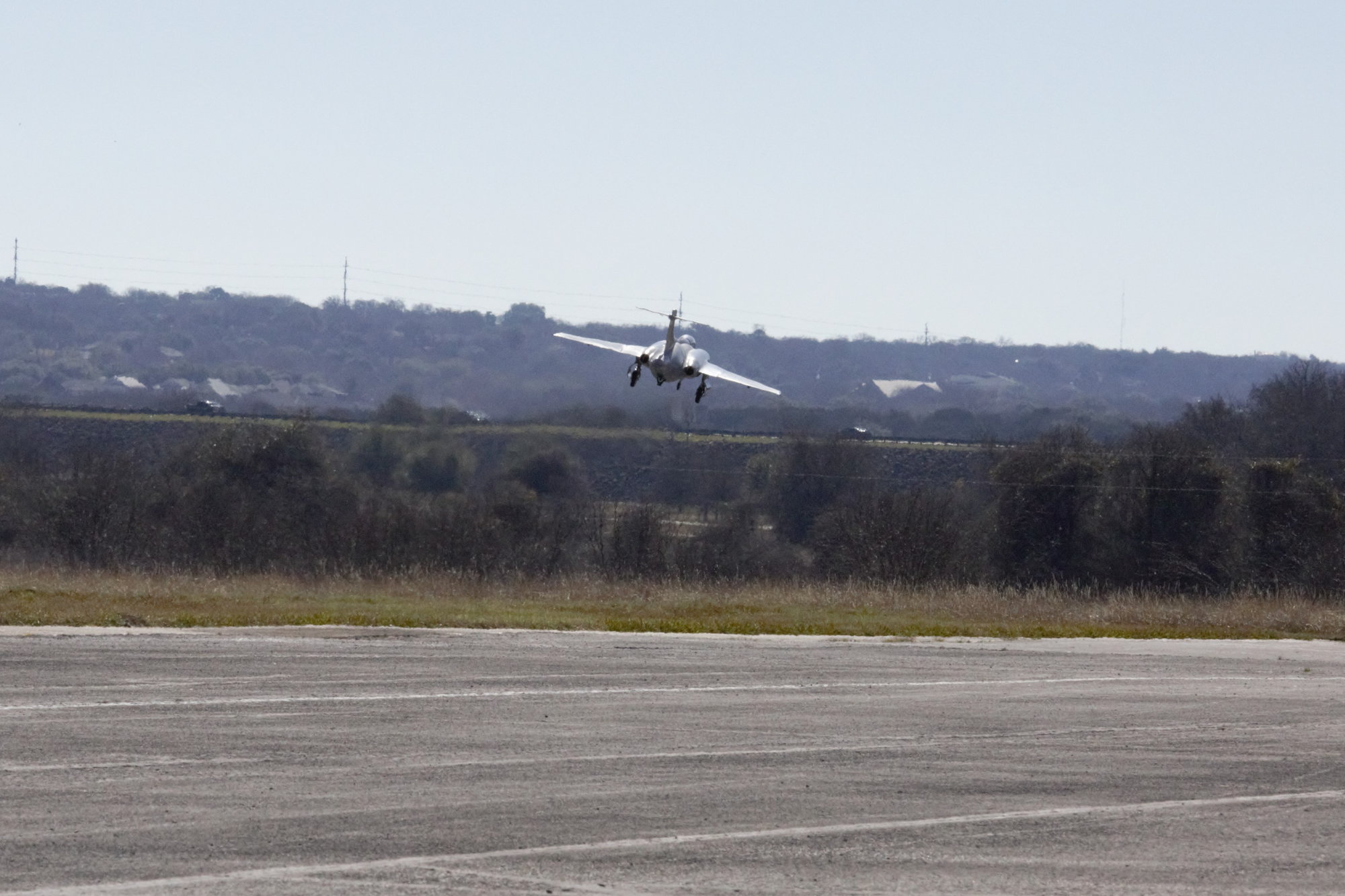
After a couple of laps, I selected take-off flap. Flap travel speed (up to mid/ take-off) was set to 10sec and minimal transients were seen. Some minor re-trimming was needed, but it felt very stable. Roll was again very sensitive.
Throughout, pitch stability felt fine - solid and not sensitive, so the calculated c.g. position that corresponded to approx 6% stability margin worked well. I did not notice any Dutch Roll motion that can be common with swept wing aircraft.
After a couple of laps with take-off flap, I decided to bring in the gyro and with nominal settings it immediately tamed the roll axes. It became very smooth and predictable.
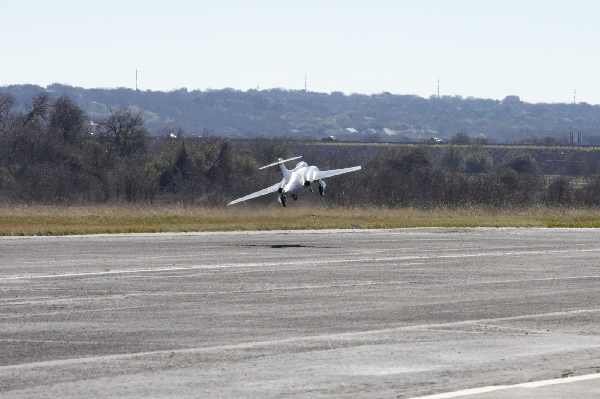
Positive climb away
Flaps Up
Mid/ Take-Off Flap
To be continued.........
I completed engine off and engine running range checks, taxi steering check plus a Jeti Assist gyro check as there have been plenty of reports of the Jeti Assist gyro suffering from acoustic pickup causing jittering surfaces. No issue at idle and low power, but jittering was apparent on all surfaces at high power. Turning the gain down to zero stopped the jittering. I reasoned that I would keep the gyro active with gain to zero, so that I could activate the gyro if needed, reasoning that if I needed the gyro to smooth out the model, that was more critical than the small possibility of the high frequency jittering causing issues at the slow speeds of the first flight. But something to fix for future flights.
The initial take off was done flaps up. The take off was great - tracked straight and the rotation was smooth with a positive climb away. Roll was very sensitive due to the full-span ailerons, even with 60% rates and 20% expo, so I induced a couple of roll oscillations until I got in sync with it. Some minor trimming in pitch and roll was needed to get it flying hands off.
Keeping the gear down for the entire flight, I reduced power to about 50% midway on downwind and it settled into a comfortable speed. I flew a couple of laps getting the feel for it, adjusting my gains to accommodate the sensitive ailerons and to fine tune the trims.
After a couple of laps, I selected take-off flap. Flap travel speed (up to mid/ take-off) was set to 10sec and minimal transients were seen. Some minor re-trimming was needed, but it felt very stable. Roll was again very sensitive.
Throughout, pitch stability felt fine - solid and not sensitive, so the calculated c.g. position that corresponded to approx 6% stability margin worked well. I did not notice any Dutch Roll motion that can be common with swept wing aircraft.
After a couple of laps with take-off flap, I decided to bring in the gyro and with nominal settings it immediately tamed the roll axes. It became very smooth and predictable.
Positive climb away
Flaps Up
Mid/ Take-Off Flap
To be continued.........
Last edited by JSF-TC; 02-07-2021 at 05:25 PM.

 02-07-2021, 05:44 PM
#587
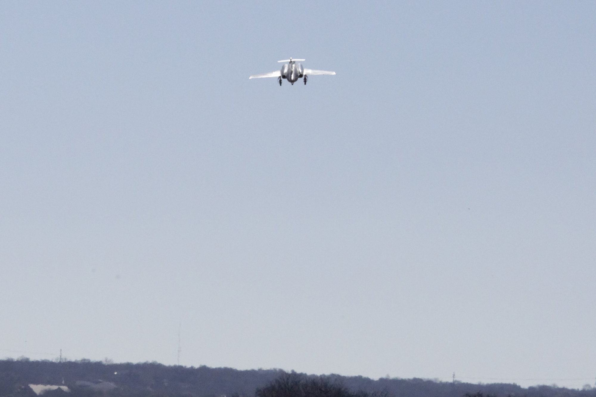
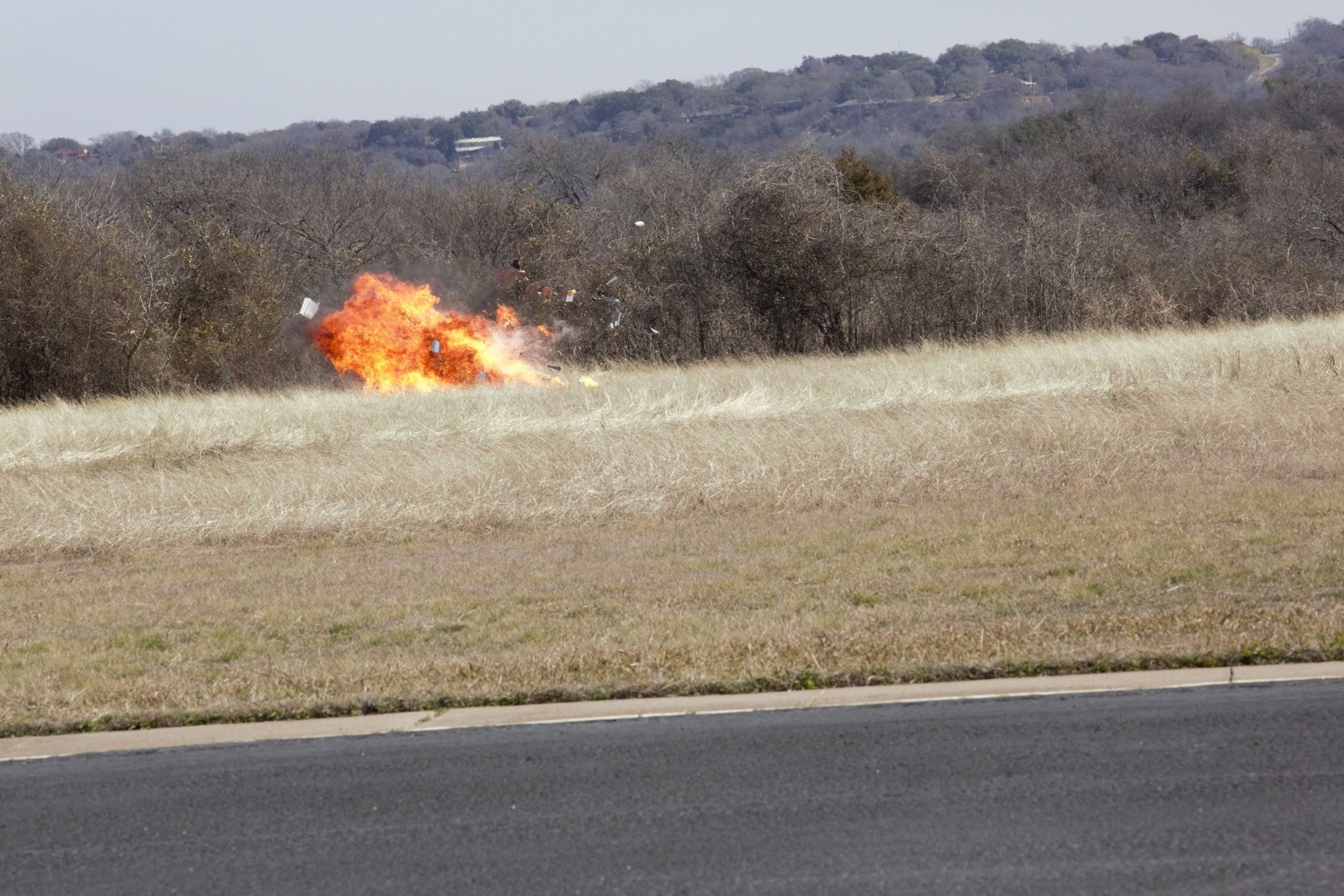
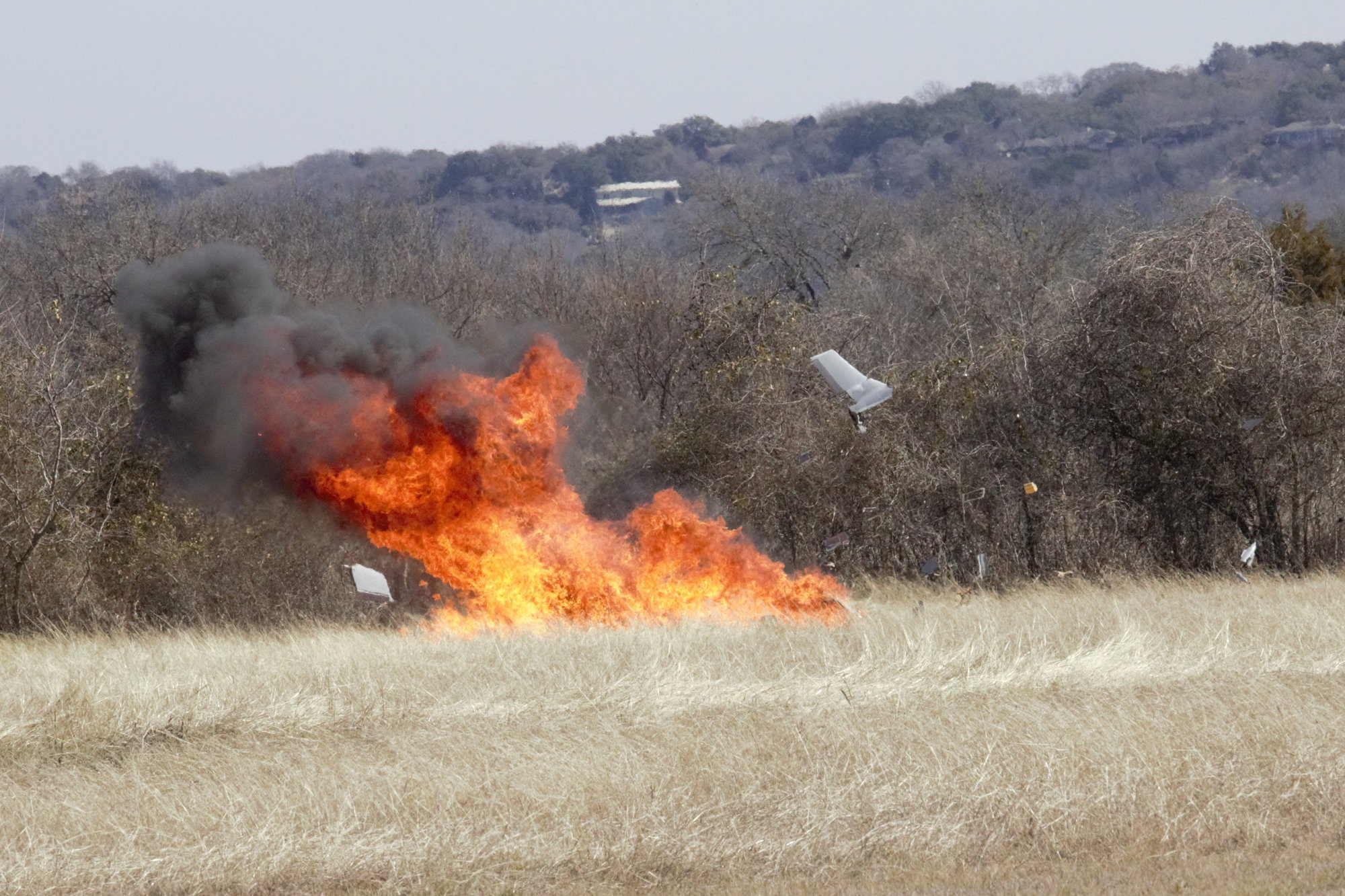
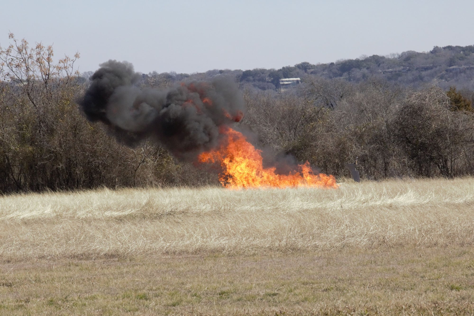
After a few laps in both flaps up and take off flap and getting it trimmed and settled, it was time to select full flap before setting up for landing. After turning onto downwind I selected full/ landing flap. Again, the mid-full travel speed was set to 10sec and I flew a steady downwind leg without the need for significant re-trimming. Turning onto upwind for a level trimming pass the plane started to feel unsettled. The turn was normal, but on rolling out the nose dipped slightly and it settled into a descending flight path. Attempting to correct with up elevator failed to correct it, and the dive steepened.
On reaching full up elevator with no effect, I grabbed for flaps up. Unfortunately, with the 10sec travel speed, nothing seemed to change the flight path and the plane impacted mid-field at high power with an immediate fireball. There was a significant grass fire and rushing over with fire extinguishers, the group of us put out the fire, but the model was totally destroyed. The 2 motors and the main gear were the only recognizable pieces remaining.
Full Flap
Last edited by JSF-TC; 02-07-2021 at 06:31 PM.
02-07-2021, 07:03 PM
#588
My Feedback: (20)
Paul,
So sorry to here about the loss of your Buc. It was a masterpiece of design, engineering, and craftsmanship. I hope you can figure out what may have happened to cause the loss. I learned a lot by following your build. Thank you for taking the time to share it. I'm hoping after some time you can try it again.
Gary
02-07-2021, 07:55 PM
#589
Hi Paul.
Sorry for the loss.
I hope that you had a good telemetry system that will get you all the data you need to secure the next prototype.
At this stage in the design cycle, you are in good shape.
You know your takeoff speed, control trimming, control throws and you have a first idea of the CG.
The next plane will be lighter, more optimized for CG and reliability.
The accident was caused by a loss of stabilizer authority.
This could be due to a number of things that could be coupled or not, including:
. Too forward CG + too slow
. Stabilizer masking by the flaps ( unlikely given the position of the stab unless AOA was extremely high )
. Plain simple flat stall,
If you could publish the telemetry data and video of the flight, it could help to troubleshoot.
For info, I published an article about test flight programs a long while ago:
https://www.ultimate-jets.net/blogs/...ols-on-rc-jets
Keep up with the good work!
Last edited by olnico; 02-07-2021 at 08:02 PM.
02-07-2021, 08:33 PM
#590
Thanks for the comments Guys. Appreciate it.
I had already started laying up a v2. Flaps, rudder and hatches complete so far. Going to keep going, even after today. I've not lost the drive - this is just a minor (ok - major) setback.
Oli - I've looked at the photos and the telemetry logged in my Jeti in an attempt to work out what happened.
I agree with you that tailplane blanking is unlikely given the high-mounted tail.
A tailplane stall due to downwash induced from the flaps is a likely possibility - people forget that the flow at the tailplane will have a significant downwards vector due to flow over the wing, further pronounced when the flaps are deflected, causing the local flow to potentially have a very severe downwards flow angle, which can lead to tailplane stall, loss of tailplane downforce and a subsequent drop in the nose and no elevator authority.
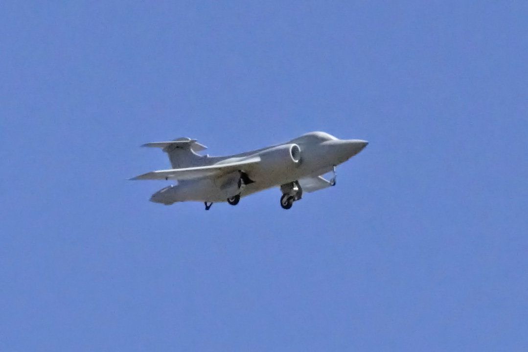
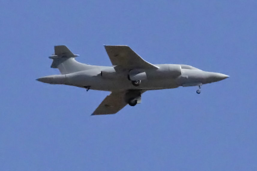
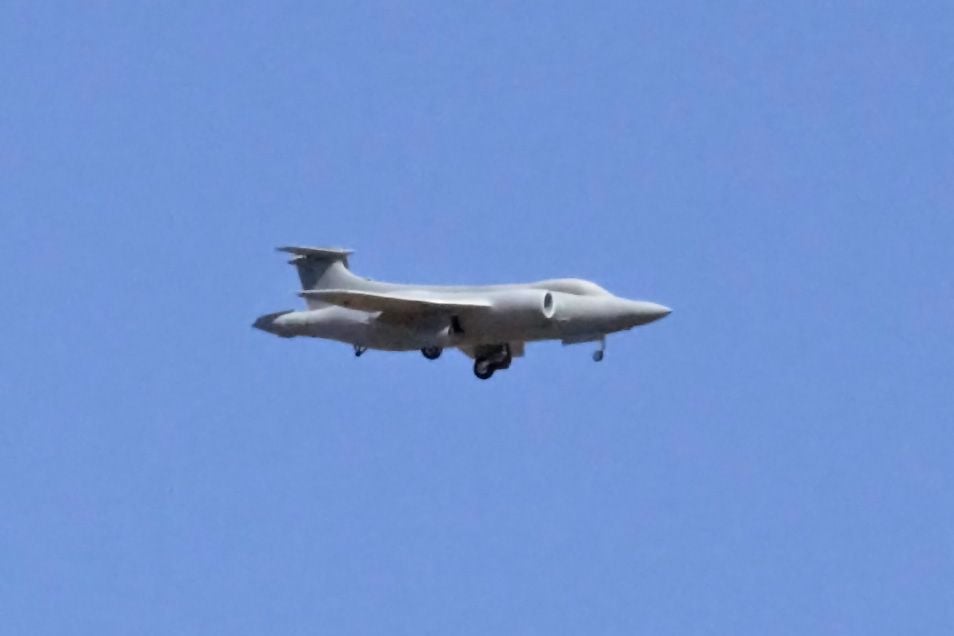
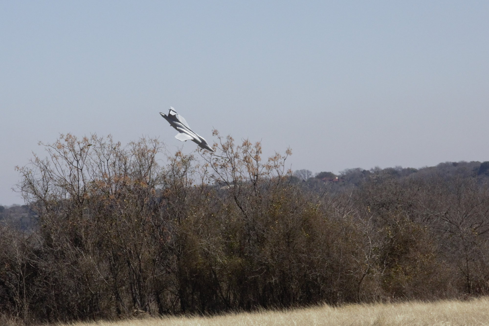
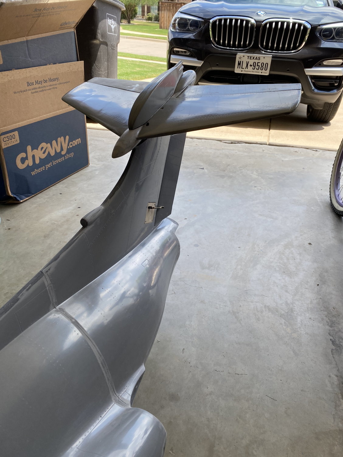
The photos below show the tailplane with flaps up, mid flap, full flap and just before impact. The before impact photo is rotated so as to be able to be compared to the others.
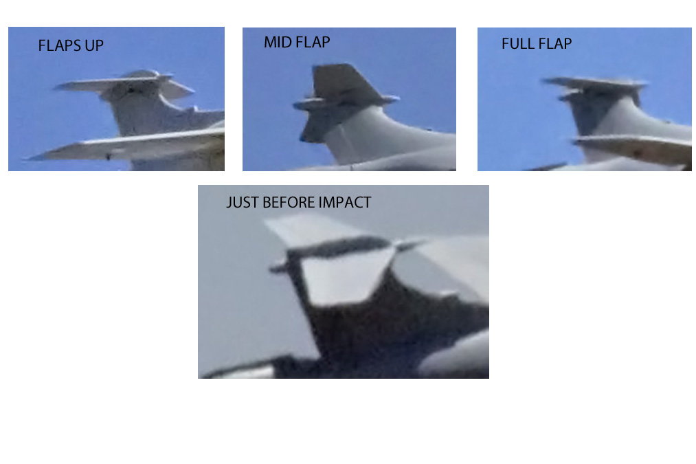
Even though I recall pulling back hard in order to stop the dive, the last photo does not appear to show a nose up tailplane position - it seems like all the others. Unfortunately I didn't have the DS-24 set to record control inputs, so I can't plot out elevator command.
When I look at the Jeti telemetry the current draw is less than 1amp before take off and in-flight with flaps up, about 3A with mid-flap and an increase in current to 5A with full flap and a couple of suspicious spikes to nearly 9A just before impact.
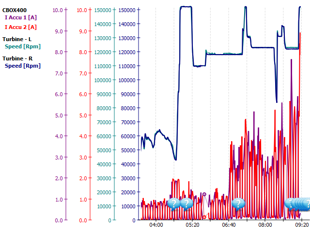
The data below is just a zoomed in view of the last part of the flight
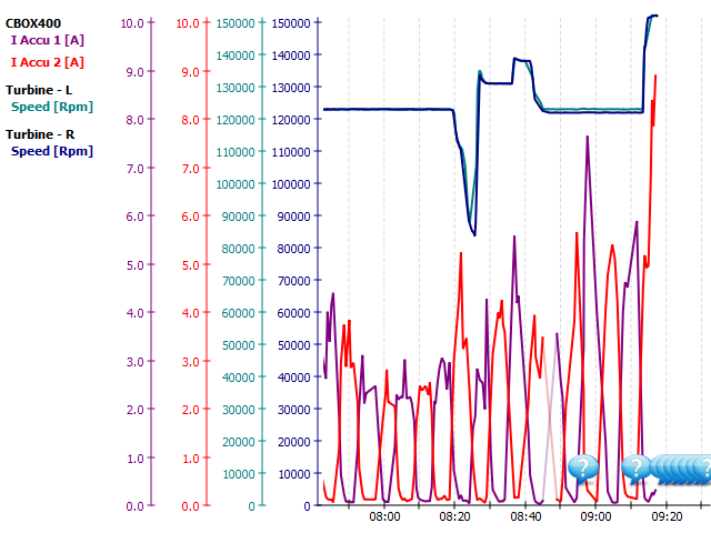
No faults or over-current flags were set by the CB400, but the 9A current draw is suspicious.
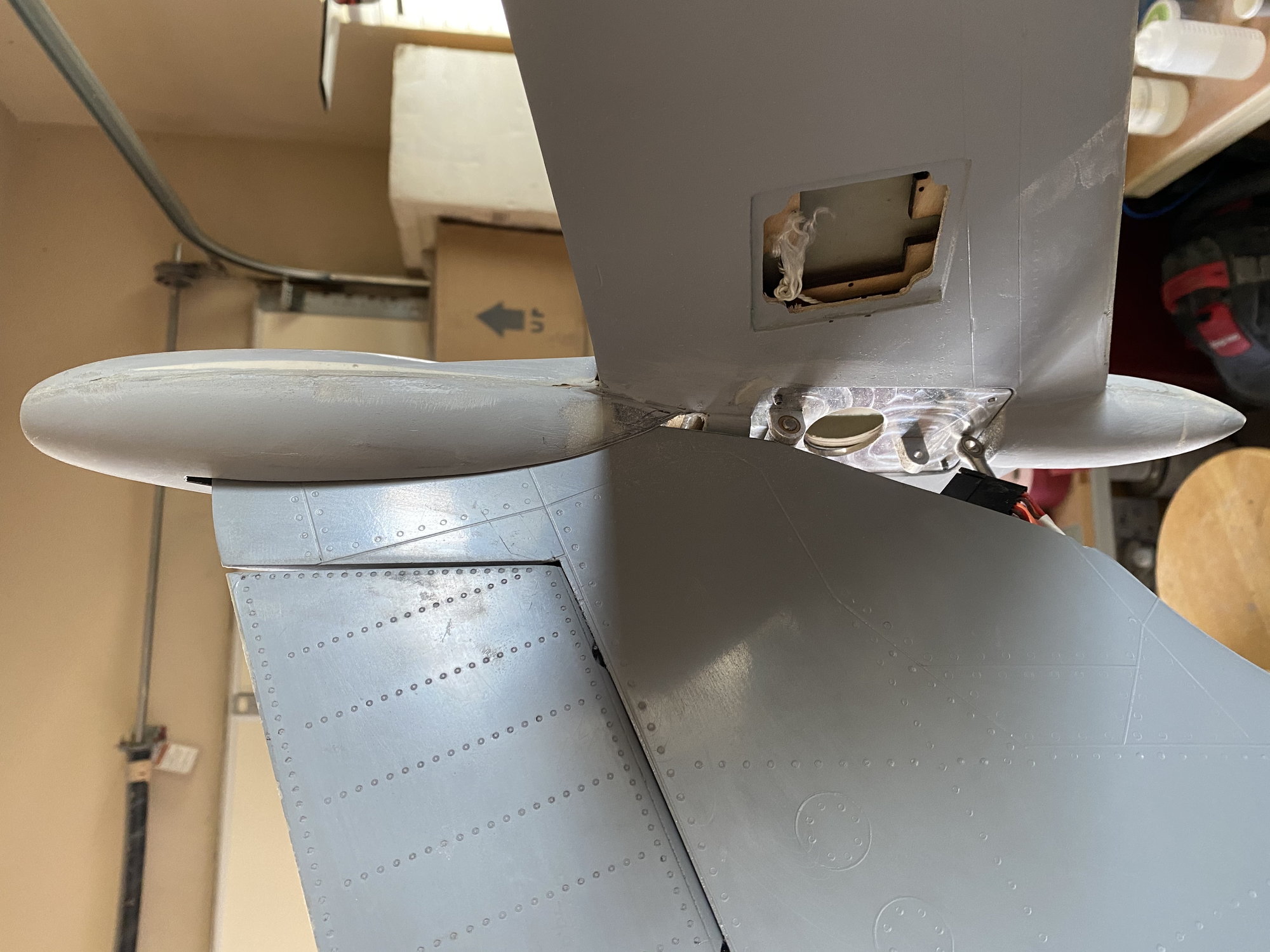
Combining the photos of the tailplane position with the current draw, I am leaning towards a theory that infers either the tailplane jammed or the servo failed, thereby preventing being able to get the commanded nose-up tailplane angle. An MKS 777+ servo was used and it exceeded the LTMA torque requirements.
I don't think there is enough data to conclusively point to either tailplane stall due to flap deflection or to a jammed tailplane/ failed servo.
The full-scale used high-pressure air for surface blowing on the wing leading edge, trailing edge flaps and tailplane leading edge to increase lift at slow speeds. I have read that the full-scale had issues if the blow was lost with the full flap deflections - I recall that running out of tailplane authority was the first major issue. I am not running the same flap deflections as full scale in part to avoid this issue, but maybe I need to reduce the full flap travel even more.
Paul
I had already started laying up a v2. Flaps, rudder and hatches complete so far. Going to keep going, even after today. I've not lost the drive - this is just a minor (ok - major) setback.
Oli - I've looked at the photos and the telemetry logged in my Jeti in an attempt to work out what happened.
I agree with you that tailplane blanking is unlikely given the high-mounted tail.
A tailplane stall due to downwash induced from the flaps is a likely possibility - people forget that the flow at the tailplane will have a significant downwards vector due to flow over the wing, further pronounced when the flaps are deflected, causing the local flow to potentially have a very severe downwards flow angle, which can lead to tailplane stall, loss of tailplane downforce and a subsequent drop in the nose and no elevator authority.
The photos below show the tailplane with flaps up, mid flap, full flap and just before impact. The before impact photo is rotated so as to be able to be compared to the others.
Even though I recall pulling back hard in order to stop the dive, the last photo does not appear to show a nose up tailplane position - it seems like all the others. Unfortunately I didn't have the DS-24 set to record control inputs, so I can't plot out elevator command.
When I look at the Jeti telemetry the current draw is less than 1amp before take off and in-flight with flaps up, about 3A with mid-flap and an increase in current to 5A with full flap and a couple of suspicious spikes to nearly 9A just before impact.
The data below is just a zoomed in view of the last part of the flight
No faults or over-current flags were set by the CB400, but the 9A current draw is suspicious.
Combining the photos of the tailplane position with the current draw, I am leaning towards a theory that infers either the tailplane jammed or the servo failed, thereby preventing being able to get the commanded nose-up tailplane angle. An MKS 777+ servo was used and it exceeded the LTMA torque requirements.
I don't think there is enough data to conclusively point to either tailplane stall due to flap deflection or to a jammed tailplane/ failed servo.
The full-scale used high-pressure air for surface blowing on the wing leading edge, trailing edge flaps and tailplane leading edge to increase lift at slow speeds. I have read that the full-scale had issues if the blow was lost with the full flap deflections - I recall that running out of tailplane authority was the first major issue. I am not running the same flap deflections as full scale in part to avoid this issue, but maybe I need to reduce the full flap travel even more.
Paul
Last edited by JSF-TC; 02-07-2021 at 08:36 PM.
02-07-2021, 09:34 PM
#591
Thanks for the comments Guys. Appreciate it.
I had already started laying up a v2. Flaps, rudder and hatches complete so far. Going to keep going, even after today. I've not lost the drive - this is just a minor (ok - major) setback.
Oli - I've looked at the photos and the telemetry logged in my Jeti in an attempt to work out what happened.
I agree with you that tailplane blanking is unlikely given the high-mounted tail.
A tailplane stall due to downwash induced from the flaps is a likely possibility - people forget that the flow at the tailplane will have a significant downwards vector due to flow over the wing, further pronounced when the flaps are deflected, causing the local flow to potentially have a very severe downwards flow angle, which can lead to tailplane stall, loss of tailplane downforce and a subsequent drop in the nose and no elevator authority.
The photos below show the tailplane with flaps up, mid flap, full flap and just before impact. The before impact photo is rotated so as to be able to be compared to the others.
Even though I recall pulling back hard in order to stop the dive, the last photo does not appear to show a nose up tailplane position - it seems like all the others. Unfortunately I didn't have the DS-24 set to record control inputs, so I can't plot out elevator command.
When I look at the Jeti telemetry the current draw is less than 1amp before take off and in-flight with flaps up, about 3A with mid-flap and an increase in current to 5A with full flap and a couple of suspicious spikes to nearly 9A just before impact.
The data below is just a zoomed in view of the last part of the flight
No faults or over-current flags were set by the CB400, but the 9A current draw is suspicious.
Combining the photos of the tailplane position with the current draw, I am leaning towards a theory that infers either the tailplane jammed or the servo failed, thereby preventing being able to get the commanded nose-up tailplane angle. An MKS 777+ servo was used and it exceeded the LTMA torque requirements.
I don't think there is enough data to conclusively point to either tailplane stall due to flap deflection or to a jammed tailplane/ failed servo.
The full-scale used high-pressure air for surface blowing on the wing leading edge, trailing edge flaps and tailplane leading edge to increase lift at slow speeds. I have read that the full-scale had issues if the blow was lost with the full flap deflections - I recall that running out of tailplane authority was the first major issue. I am not running the same flap deflections as full scale in part to avoid this issue, but maybe I need to reduce the full flap travel even more.
Paul
02-08-2021, 01:58 AM
#592

Really sorry to hear of your loss, tragic.
I am not going to try to determine the cause, but that 9 amp looks suspicious and I base that on having monitored currents on my large jets via Weatronics data recording. Dont think I have ever seen 9 amps, 7 max during flap extension on the big Hawk.
May I ask what landing flap angle you were using ? A large flap angle causing a nose down pitch, could simply exceed the tailplane authority.
That actually happened on the first flight of the real BAe Hawk, which led to SMURFS and the cutout of the Hawk flap vane, although flap downwash was that cause of loss of tailplane effectiveness.
Having flown one large T tailed airliner, I think tailplane blanking unlikely, but not impossible. The T tail. Problem, leading to locked -in superstall ( which led to the loss of a Trident and BAC 1-11) occurred at very high pitch angles.
So. again, my sincerest sympathy for your loss of this superb project and I do hope we will see V 2 soon.
02-08-2021, 05:12 AM
#593

Paul
Sorry to hear this. Sounds like most of the flight was positive though? Not to "armchair pilot" this too much, it appears the speedbrake was open -ish in the still images... was it open or was that a shadow?
I think you have documented a few adjustments and can pull together an even better one.
Ron's slow, float him a few plugs to pull parts out of!!
02-08-2021, 06:09 AM
#594

Were the motors at least thrown free of the fire such that they're serviceable I hope?
Also, very impressed you guys got to that fire and were able to limit the spread. Hard to judge but from the pics it looks like it was pretty far across the field and that grass looks ripe for a much faster spread with a little breeze.
Echoing the others, sorry about the plane but you're definitely doing some real test pilot stuff here. Can't wait to see you build it stronger and lighter the next time around.
02-08-2021, 07:02 AM
#595
Oli - log file attached. Remove the .txt extension to open it in Jeti Studio.
David - I initially was going to use the full scale deflections, 45deg Flap/ 25deg Aileron/ 25deg HT Flap, but these looked way to much, especially considering I don't use surface blowing, so I backed off some to something that looked a bit more reasonable. I didn't measure them (apart from ensuring symmetry), but I would estimate flaps were around 35-40deg, ailerons no more than 10deg, and HT Flap was 15-20deg with full flap selected. Mid/ takeoff flap was around half of that.
They were in the burnt debris field, both are dented and damaged but they both rotate, albeit one with some resistance. Electronics and pumps are gone. They are worth sending in for an assessment to be repaired.
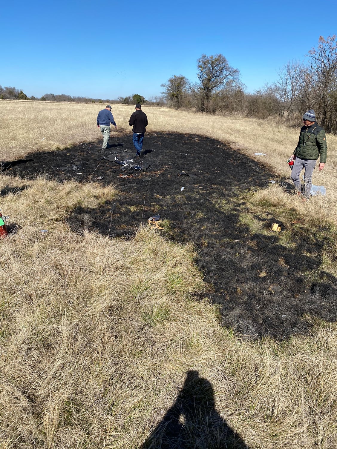
There was a reasonable breeze, but we started from the downwind edge and worked back upwind to limit the spread of the fire. We all got our exercise for the day!
As a lesson learned, all clubs should consider having some of those firefighter beaters to held put out the grass fires. We had 4 pressurized water extinguishers that we used up and had to revert to our CO2 ones. Indian fire extinguishers may be better as they hold more water.
Paul
May I ask what landing flap angle you were using ?
Were the motors at least thrown free of the fire such that they're serviceable I hope?
There was a reasonable breeze, but we started from the downwind edge and worked back upwind to limit the spread of the fire. We all got our exercise for the day!
As a lesson learned, all clubs should consider having some of those firefighter beaters to held put out the grass fires. We had 4 pressurized water extinguishers that we used up and had to revert to our CO2 ones. Indian fire extinguishers may be better as they hold more water.
Paul
02-08-2021, 07:08 AM
#596
OK a, fairly, educated guess having just looked at your pictures.
Your landing flap angle caused strong nosedown pitch , increasing as speed reduced.
The small elevators on a fixed tailplane simply were insufficient to compensate, even less so as speed reduced
I have just looked at a picture of an RN Buccaneer landing, it has huge elevator deflection plus large negative TPI suggesting that the nosedown pitch in landing Config is substantial. As you know HS “blew” the tailplane as well as the wing. Later F4s made their slab tailplane even more powerful by adding an inverted slat on theTP LE.
So perhaps an all moving tailplane coupled to flap deflection, a sort of datum shift as on the Gnat, might be an idea with V 2.
Anyway, good luck with the model, you certainly deserve it.
02-08-2021, 07:29 AM
#597
Join Date: Aug 2009
Location: Cape Town, SOUTH AFRICA
Posts: 504
Likes: 0
Received 2 Likes
on
2 Posts
Just terrible to see...Do not under estimate the airflow around the exhaust ducts having an effect on the flaps loading. Air accelerated by the exhaust so close to flaps may cause that current draw. ie lower pressure above, high pressure below flaps....
Then also the effect it has on rear of fuselage could change drastically depending on AOA.
Brg
Andre
Then also the effect it has on rear of fuselage could change drastically depending on AOA.
Brg
Andre
02-08-2021, 07:39 AM
#598
The small elevators on a fixed tailplane simply were insufficient to compensate, even less so as speed reduced
So perhaps an all moving tailplane coupled to flap deflection, a sort of datum shift as on the Gnat, might be an idea with V 2.
Maybe just your wording, but I think you are assuming that the only pitch control for the model were the small tailplane flaps.
That is incorrect - the primary pitch control is an all-moving tailplane. The small tailplane trailing edge flaps only deflect (up) as a flap when the wing flaps deploy (down) to act as a trim device. The trailing edge flaps do not respond to pitch control inputs.
Paul
02-08-2021, 09:20 AM
#599
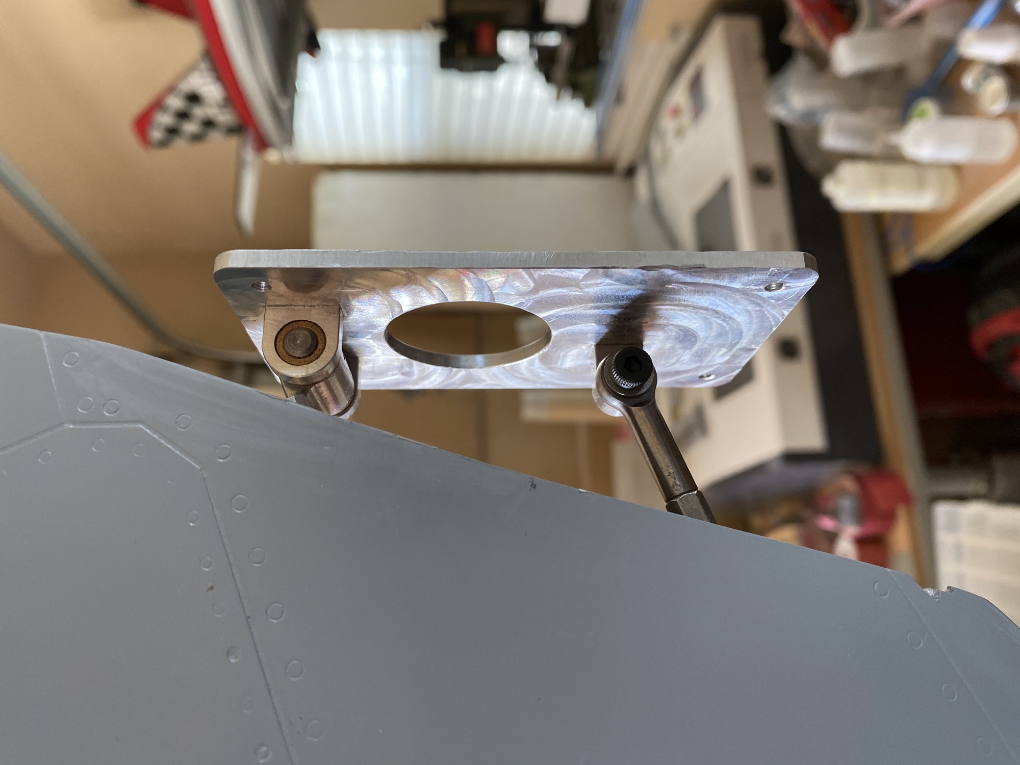
Based on the second pic in the above post and the last pic of the model in air descending towards it's unfortunate demise, at least with my eyes it looks like there is almost no upward deflection of the flying stab. I'm inclined to believe you had a stab servo failure. Was that a single servo driving the stab or a pair of ganged servos?
02-08-2021, 09:27 AM
#600
Agreed. Just a single MKS 777+. The photos and the 9A current draw spikes also lead me to the suspicion of a servo failure or a jammed surface that stalled the servo.
506oz.in torque vs. a min requirement of 306oz.in required by the LTMA rules, so aerodynamic forces shouldn't have been an issue..
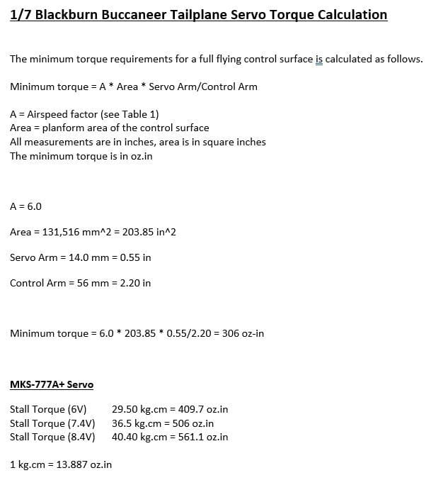
506oz.in torque vs. a min requirement of 306oz.in required by the LTMA rules, so aerodynamic forces shouldn't have been an issue..