


1/7 Scale Blackburn Buccaneer All Composite Scratch Build
 08-15-2020, 01:17 PM
#451

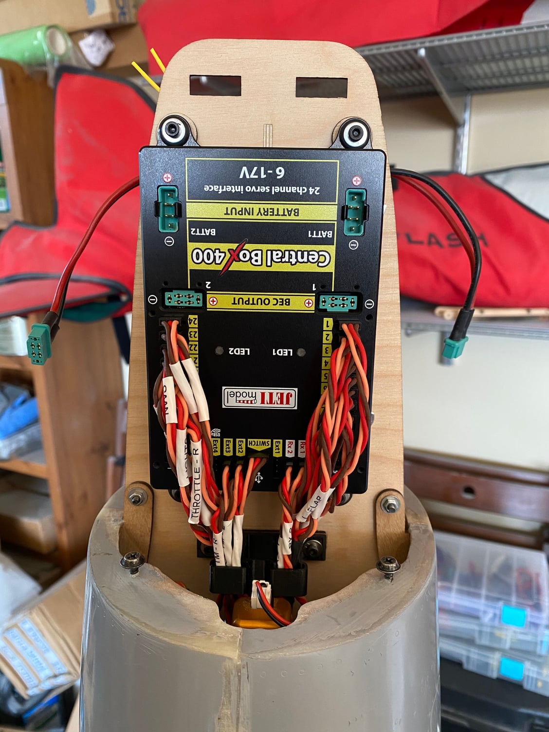
I've started on the wiring, something not messy that can be done in the house whilst it is 105F+ in the garage at the moment.
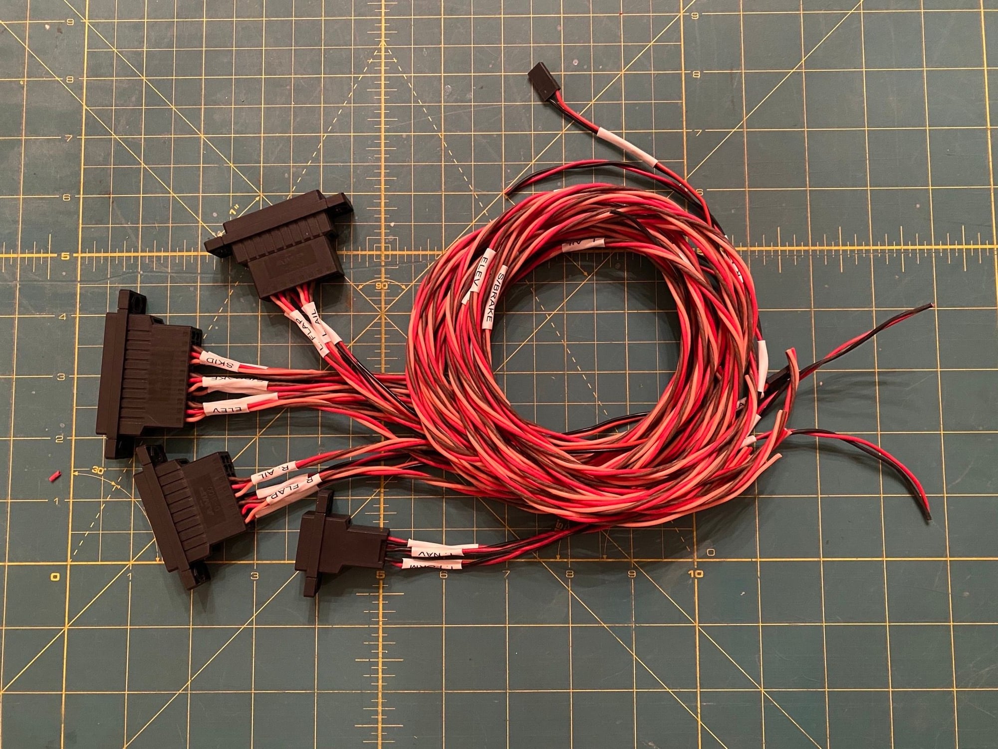
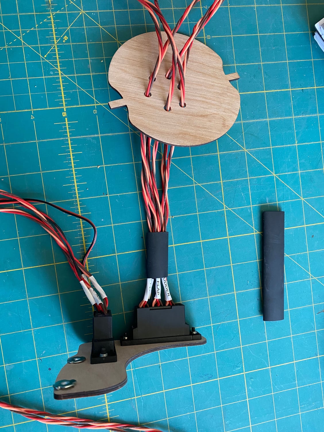
I decided on main disconnects at each major fuselage break in order to allow relatively easy assembly/ dis-assembly. AMP connectors were used for these. They are nice but a bit on the large size. Disconnect brackets were added to hold the harnesses/ connectors in place.
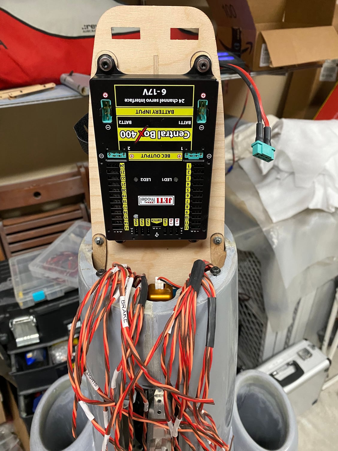
In order to bundle up the wires into manageable harnesses without the wires all crossing over each other, I made a wire comb to keep them separated as I shrunk the heat-shrink tubing over them. Each wire was individually labeled with heat shrink labels at each end using a Dymo label maker. Right now, they all run forward waiting to be terminated at the Jeti CB400 power box in the radome. Wiring for lights has been included, but I will add the lights once I get to finishing the model, after the tests flights.
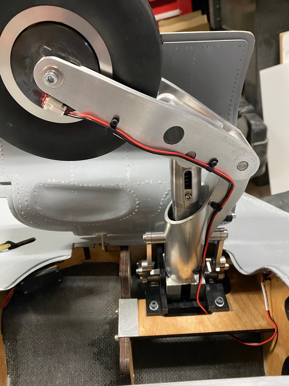
The brake wiring was run down the gear legs and attached with micro P-clips and 2mm screws.


I decided on main disconnects at each major fuselage break in order to allow relatively easy assembly/ dis-assembly. AMP connectors were used for these. They are nice but a bit on the large size. Disconnect brackets were added to hold the harnesses/ connectors in place.
In order to bundle up the wires into manageable harnesses without the wires all crossing over each other, I made a wire comb to keep them separated as I shrunk the heat-shrink tubing over them. Each wire was individually labeled with heat shrink labels at each end using a Dymo label maker. Right now, they all run forward waiting to be terminated at the Jeti CB400 power box in the radome. Wiring for lights has been included, but I will add the lights once I get to finishing the model, after the tests flights.
The brake wiring was run down the gear legs and attached with micro P-clips and 2mm screws.
Last edited by JSF-TC; 08-15-2020 at 01:30 PM.
 08-15-2020, 01:24 PM
#452
One setback I came across was then I got around to formally working out the servo requirements per the AMA LTMA-1 rules.
The rudder was fine, but the elevator was marginal and the ailerons were woefully under powered.
The elevator needed 556ozin and I had a MKS 777+ on the elevator which gives 506ozin at 7.4V and 561ozin at 8.4V. Luckily I can drop in a MKS HBL3850 which gives 708ozin at 7.4V to solve that problem.
I had chosen MKS 747R servos for the ailerons which output 191ozin at 7.4V, but the calculations showed I needed 478ozin. Even doubling up the 747 servos wasn't enough. Luckily there is enough depth to replace the 747 servo with a 777+, but it will take some butchering of the mount to get it fitted. I will come back to that.
That was a rookie mistake that I knew I had to check for a long time. At least I have a solution for now.
Paul
08-16-2020, 05:32 AM
#453

Have you considered the Futaba HPS A700 servo ?
Over 1000oz/in at 7.4 v and with a superb gearbox and brushless motor all in a standard size metal case.
Over 1000oz/in at 7.4 v and with a superb gearbox and brushless motor all in a standard size metal case.

 08-23-2020, 07:35 AM
#455
David/ Thomas,
Thanks for the servo recommendations, although I'm going to stay with MKS for this build. Promodeler servo look great, but I've not heard much about them.
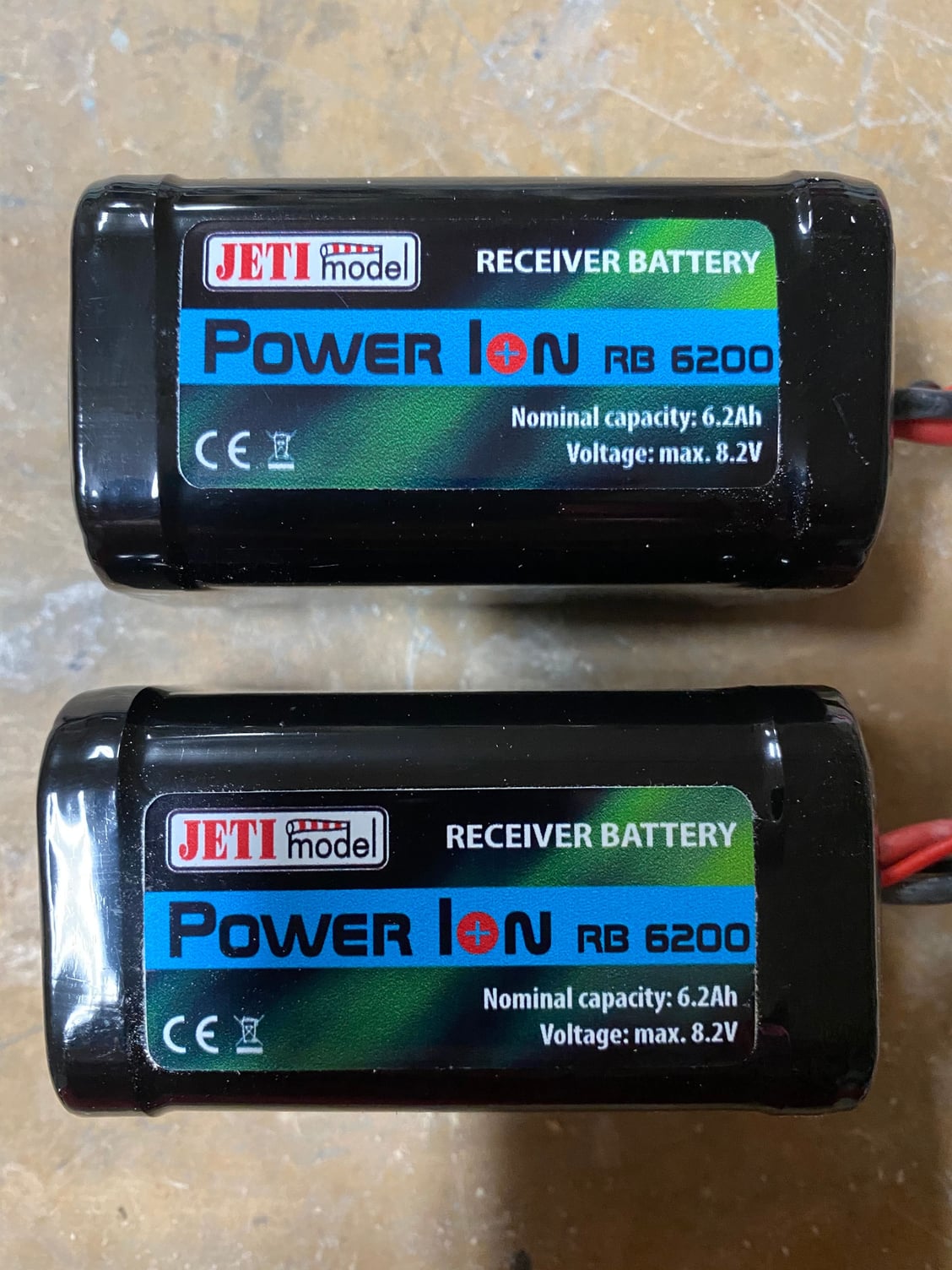
Continuing the build, the wiring is still progressing. All the servo wiring is now run to the nose and terminated and connected to the Jeti CB400. Power wiring is next up. 2 Jeti 6200mAh Li-Ion batteries to be used for all on-board systems.
Starting the radio programming, and completed the first full-up gear cycles. Still need to finalize the rigging for the nose gear door to avoid stalling the servo.


Thanks for the servo recommendations, although I'm going to stay with MKS for this build. Promodeler servo look great, but I've not heard much about them.
Continuing the build, the wiring is still progressing. All the servo wiring is now run to the nose and terminated and connected to the Jeti CB400. Power wiring is next up. 2 Jeti 6200mAh Li-Ion batteries to be used for all on-board systems.
Starting the radio programming, and completed the first full-up gear cycles. Still need to finalize the rigging for the nose gear door to avoid stalling the servo.
 08-24-2020, 07:29 AM
#458

Raf
https://smile.amazon.com/gp/product/...?ie=UTF8&psc=1
Dymo Rhino 4200. Get the 1/2" heat shring tubing label for it
https://smile.amazon.com/gp/product/...e?ie=UTF8&th=1
Great investment. much better than tacking labels to connections or tape..
https://smile.amazon.com/gp/product/...?ie=UTF8&psc=1
Dymo Rhino 4200. Get the 1/2" heat shring tubing label for it
https://smile.amazon.com/gp/product/...e?ie=UTF8&th=1
Great investment. much better than tacking labels to connections or tape..
The following users liked this post:
yeahbaby (08-24-2020)
08-24-2020, 04:35 PM
#462

My Feedback: (20)
1/6 F-105 Build Thread See post #643
Gary
08-26-2020, 01:19 PM
#463
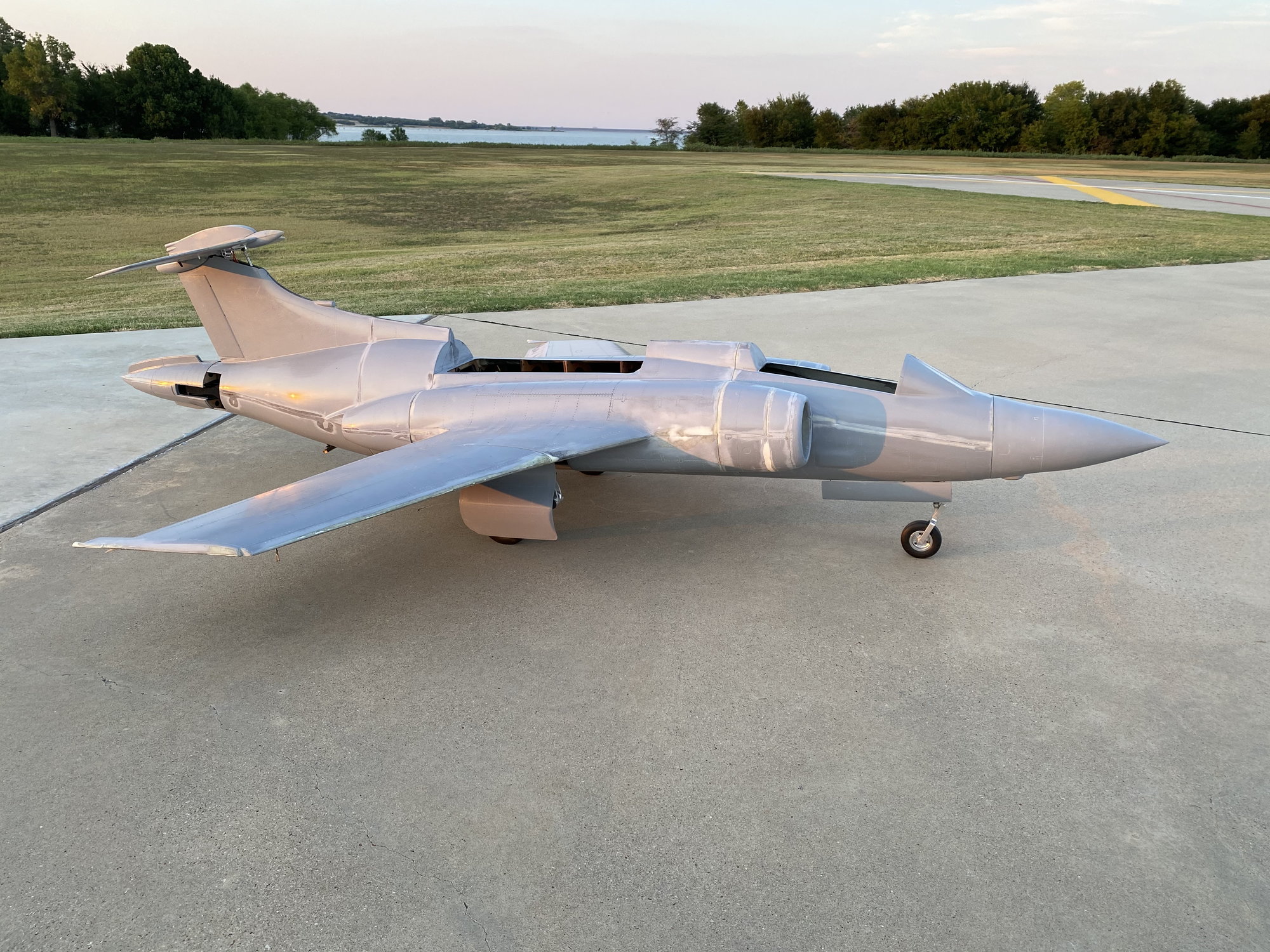
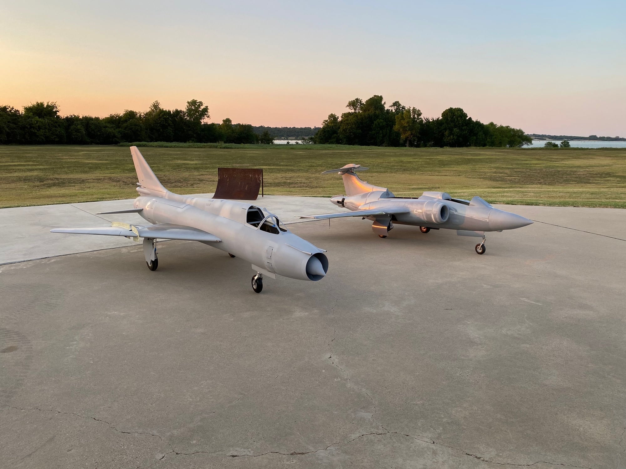
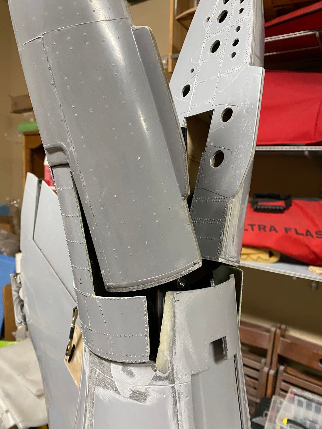
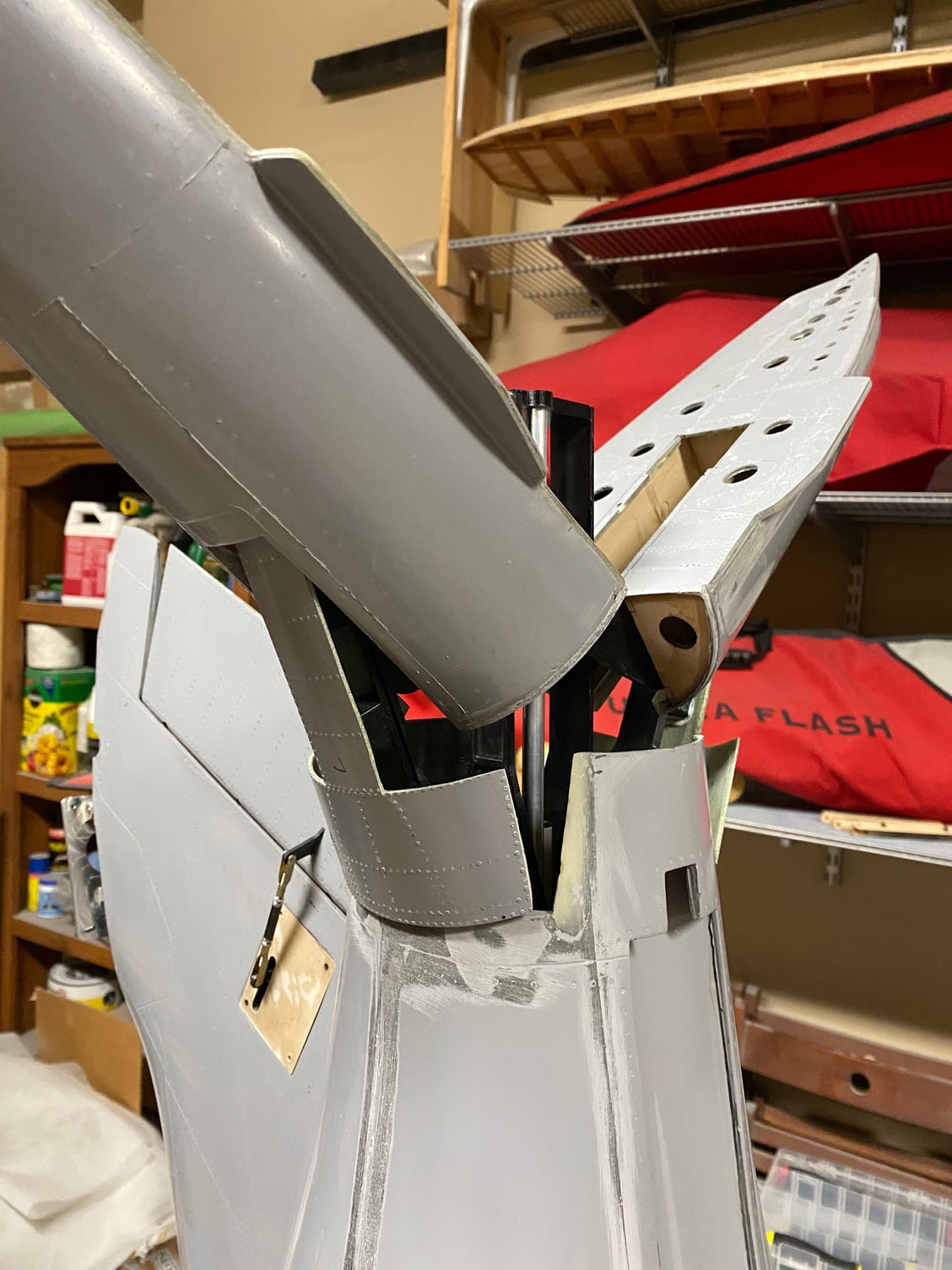
We had our monthly club meeting at the field earlier this week, so it was an opportunity to take the Buccaneer for a show-and-tell. It was also a good test for loading up the car.
Well, it wouldn't fit with the fuselage in one piece, but with either the nose or tail section removed it all fit just fine. Removing the nose section will be easier, plus it allows the tail pipes to remain protected - they would be partially exposed with the rear fuselage removed.
It was also the first time that I had had it this completely assembled and could stand back and observe it from a distance. It was apparent that I will need to stiffen up the main gear springs and potentially shorten the nose gear to get it to sit level.
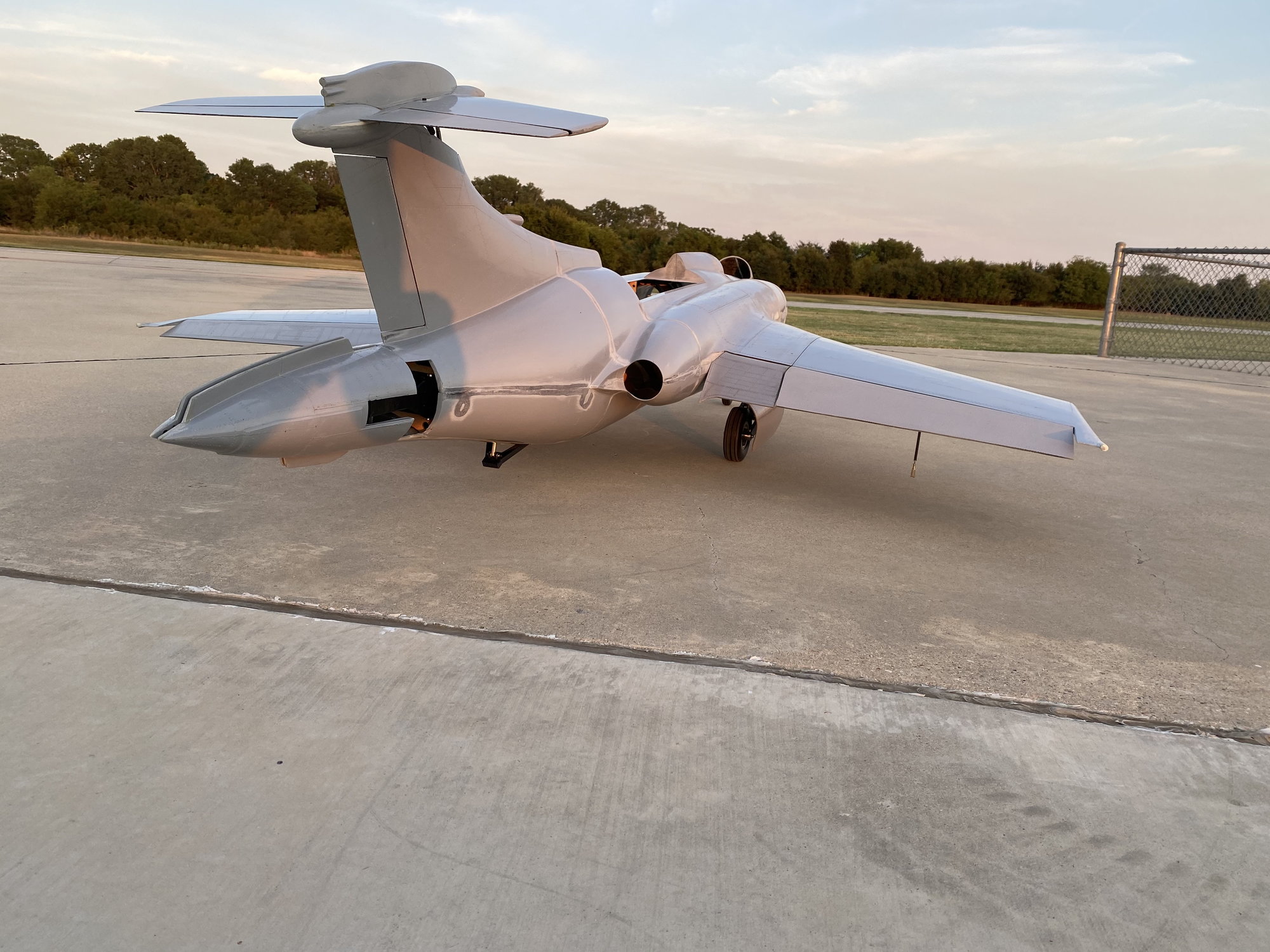
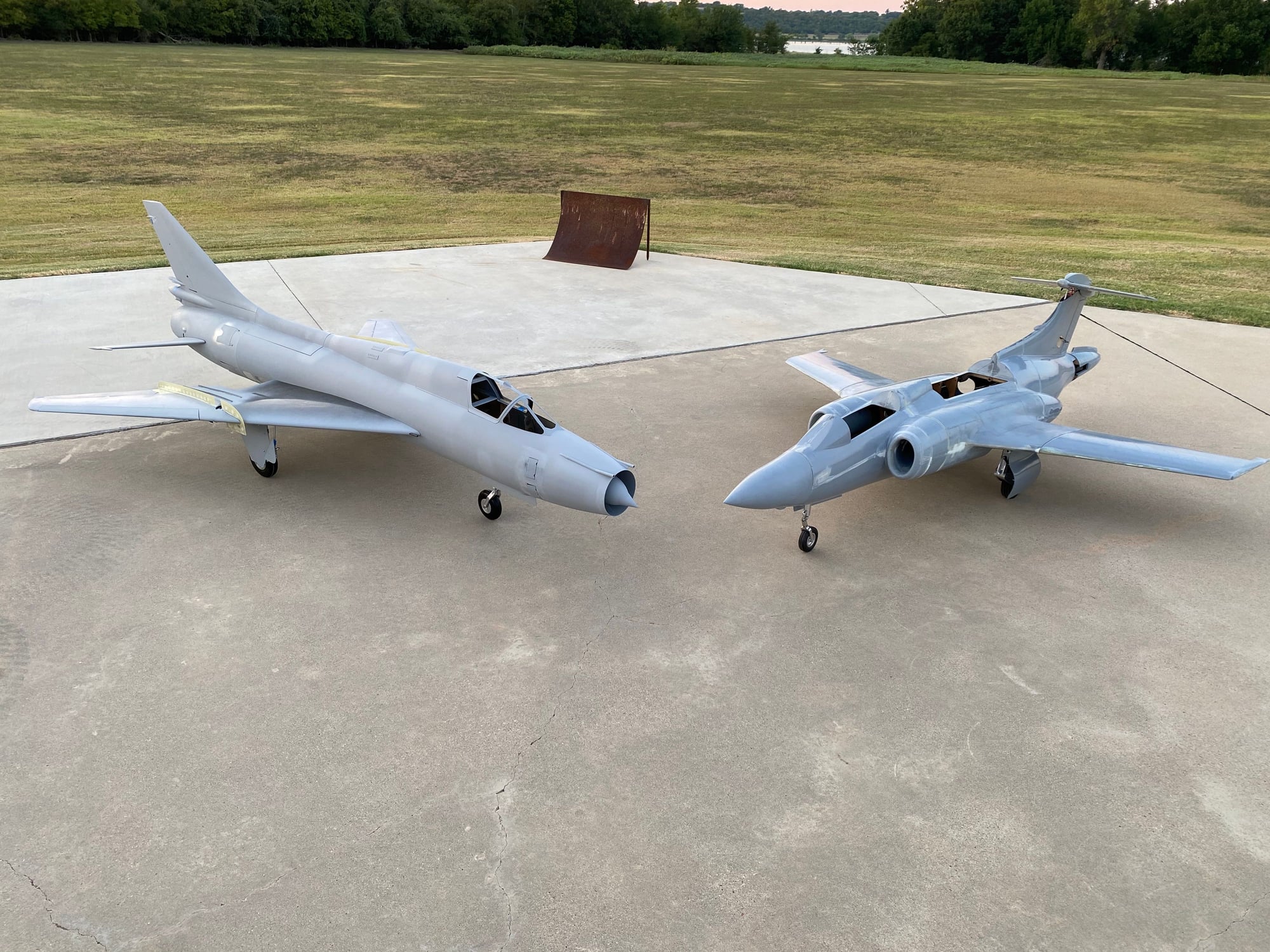
Another scratch build project broke cover also, RonS with his 1/6 scale SU-17/22. He started it around the same time that I started the Buccaneer. Fantastic model with function swing wings and leading edge flaps. It will look amazing in-flight. Keep going Ron.
Well, it wouldn't fit with the fuselage in one piece, but with either the nose or tail section removed it all fit just fine. Removing the nose section will be easier, plus it allows the tail pipes to remain protected - they would be partially exposed with the rear fuselage removed.
It was also the first time that I had had it this completely assembled and could stand back and observe it from a distance. It was apparent that I will need to stiffen up the main gear springs and potentially shorten the nose gear to get it to sit level.
Another scratch build project broke cover also, RonS with his 1/6 scale SU-17/22. He started it around the same time that I started the Buccaneer. Fantastic model with function swing wings and leading edge flaps. It will look amazing in-flight. Keep going Ron.
The following 2 users liked this post by Dave Wilshere:
Auburn02 (08-26-2020),
Jeroen.surf.nl (06-28-2021)
The following users liked this post:
Hustler58 (08-26-2020)
08-27-2020, 03:22 PM
#469

Ahh, the Sun setting on a couple Cold War Jets...  It was nice to put these in-work projects next to each other. Paul is quite a bit farther along in the build process, as he is already installing servos and wiring. I'm still building and installing wing fences... I hope we're not in a race! Maybe we can plan for another pic in a couple months. Thanks for the nice words on both projects!

It was nice to put these in-work projects next to each other. Paul is quite a bit farther along in the build process, as he is already installing servos and wiring. I'm still building and installing wing fences... I hope we're not in a race! Maybe we can plan for another pic in a couple months. Thanks for the nice words on both projects!  08-29-2020, 01:03 AM
#471
A tip, Ron, jf I may.
The Bucc. Does not have wing fences but it does have multiple vortex generators near the wing leading edge.
For these to work and assist in reenergising the boundary layer they must be set at the correct angle to generate the vortex.
I have heard of many Model Hawk fliers report nasty stalls but all three of my Hawks, 2 Airworld and 1 Skygate all have correctly placed and angled vortex generators and all 3 show totally benign stalls. They seem to work even at our Reynolds numbers. I have seen many model Hawks with VG s almost all parallel to the centerline, pretty but ineffectual.
Anyway, I pass this on for what it's worth.
Great project, watching with great interest.
08-29-2020, 04:37 PM
#472
Hi David,
It's actually Paul doing all the Buccaneer work... I suspect he has a plan how to deal with the leading edge VGs - I've just not heard what it is.
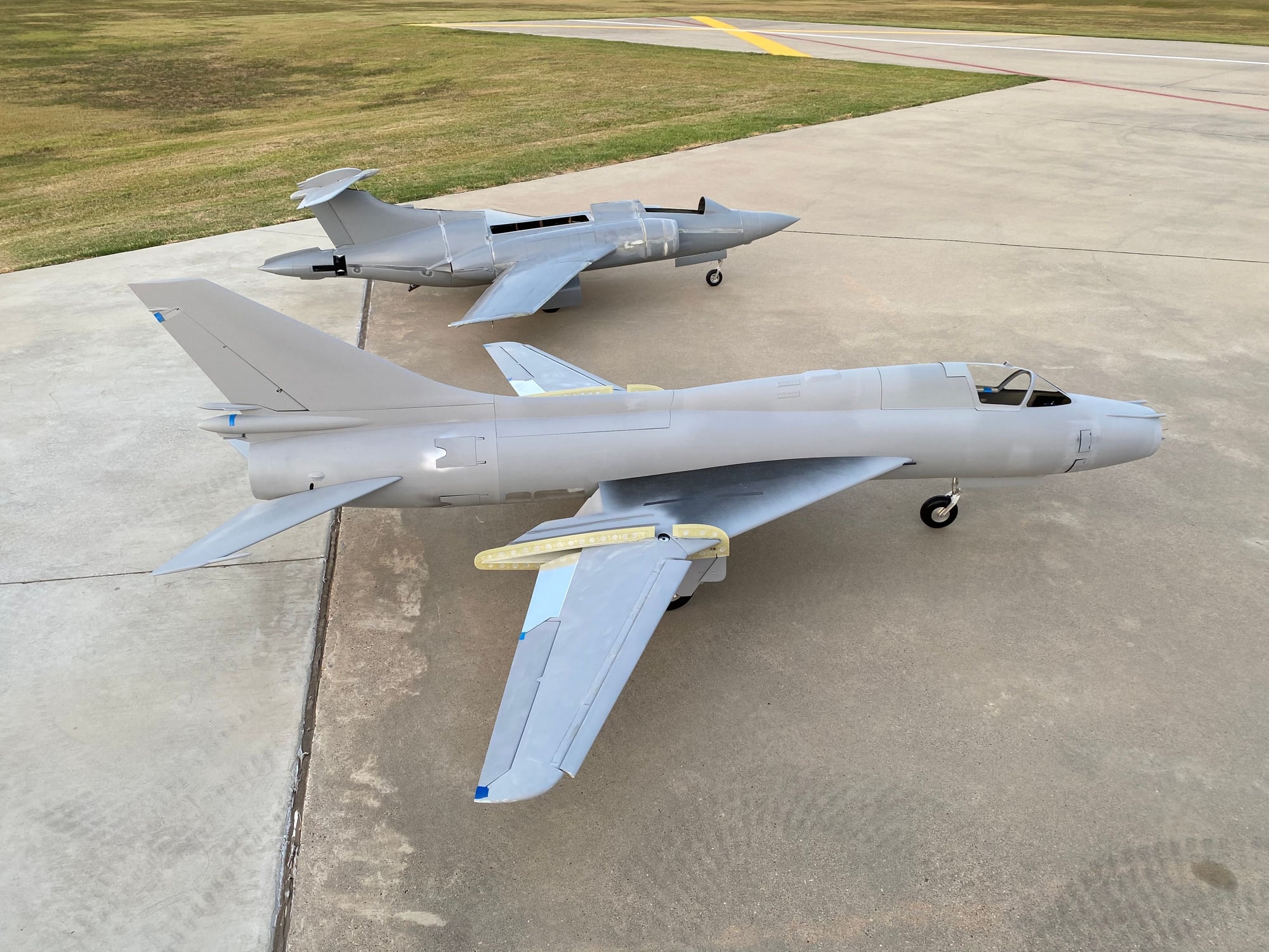
It's working up to be a neat model! And unique - atleast for the US... The VGs are visible in this pic.

It's actually Paul doing all the Buccaneer work... I suspect he has a plan how to deal with the leading edge VGs - I've just not heard what it is.
It's working up to be a neat model!
And unique - atleast for the US... The VGs are visible in this pic.
09-03-2020, 10:34 AM
#473
David,
I think at our scales, Reynolds Number and speeds, the fences are doing the majority of the work to stabilize the flow and keep it attached. My understanding is that the VG's only really work as intended at high speed to avoid the transonic separation bubble and to keep the flow attached to the upper surface.
I plan on adding the VG's, but for purely cosmetic reasons when I get to finishing and detailing the model. I incorporated 3deg washout in the wing to try to avoid any tip-stall issues. Flight testing will be the proof.
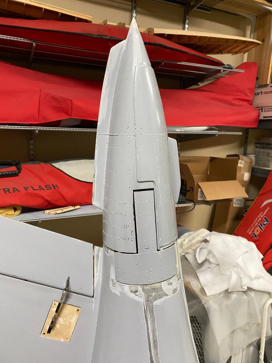
I've been working on finishing the speedbrake. Getting the drag link doors to fit and operate was like trying to get a set of gear doors to work. It took a while but it was worth it. Adding them has stiffened up the 3D printed mechanism tremendously.
I think at our scales, Reynolds Number and speeds, the fences are doing the majority of the work to stabilize the flow and keep it attached. My understanding is that the VG's only really work as intended at high speed to avoid the transonic separation bubble and to keep the flow attached to the upper surface.
I plan on adding the VG's, but for purely cosmetic reasons when I get to finishing and detailing the model. I incorporated 3deg washout in the wing to try to avoid any tip-stall issues. Flight testing will be the proof.
I've been working on finishing the speedbrake. Getting the drag link doors to fit and operate was like trying to get a set of gear doors to work. It took a while but it was worth it. Adding them has stiffened up the 3D printed mechanism tremendously.
The following users liked this post:
pilot43 (09-05-2020)
09-05-2020, 12:54 AM
#475
David,
I think at our scales, Reynolds Number and speeds, the fences are doing the majority of the work to stabilize the flow and keep it attached. My understanding is that the VG's only really work as intended at high speed to avoid the transonic separation bubble and to keep the flow attached to the upper surface.
I plan on adding the VG's, but for purely cosmetic reasons when I get to finishing and detailing the model. I incorporated 3deg washout in the wing to try to avoid any tip-stall issues. Flight testing will be the proof.
I've been working on finishing the speedbrake. Getting the drag link doors to fit and operate was like trying to get a set of gear doors to work. It took a while but it was worth it. Adding them has stiffened up the 3D printed mechanism tremendously.
https://youtu.be/mdd4HtL_S_g
Fences exist to minimise spanwise flow and its sdverse effect on the boundary layer, particularly on the outboard sections of swept wings. Early Russian Migs used them extensively. The Buccaneer with its unique, for British aircraft, �blown� wing and tail did not use them
VGs work at all speeds to help reenergise the boundary layer and extend the separation point at high angles of attack and are used on many very non transonic jets eg B737 !
VGs are now being used on even the Piper Cub,( and several other STOL aircraft) distinctly non transonic, and have been found to redUce stall speed by about 16 %, stall angle by 1 or 2 degrees and improve aileron effectiveness.
That said, they have to be set to the correct angle, about 15 degrees, to produce rotating or counter rotating vortices, I think the Bucc has them set at the same angle.
When building my first of three Hawks, Duncan Simpson, who did the first test flights of the real Hawk, sent me a book and drawings of the Hawk with all the wing dressings he and the boffins came up with to sort some initial problems on the early Hawk and covert it to the docile trainer it is.
I copied them exactly, VGs, fences, flap vanes with correct slots, flap angles and stall strips.
The result is a most docile model so I do , based on experince, believe they work in model sizes and recommend them.
Anyway I wish you the very best for first flights with this amazing project !