


1/7 Scale Blackburn Buccaneer All Composite Scratch Build
 06-13-2020, 06:00 AM
#426

Dave,
Thanks.
I agree that the next one I could build lighter, especially with a different glass lay-up. I've never done anything like this before so learning all the time.
I have now got some 6oz twill, so I think a 3oz glass, 6oz carbon and either 3 or 6oz glass construction would work well and save the resin weight. 6oz carbon is relatively cheap and significantly cheaper than 2 or 4oz, so cost is another variable I'm trying to manage.
If your Airworld L-39 has a scale wing, then the 35lb take off weight equates to 135oz/ sq. ft wing loading. That's huge and 50% higher than estimated for the Buccaneer. That gives me confidence.
The second rear fuselage skin just came out of the mold and it looks as good as the first. Just the lower skin to do now and I'll then have to finish off the internal structure design before progressing further.
Paul
 06-13-2020, 12:07 PM
#427

Paul
Even established companies learn during the first airframes produced where to add or subtract cloth. If you have ever seen the skins on a ‘re-kitted’ CARF Jet you would see how light a cloth is possible to layer to make a skin. Using a light cloth on the outside, slightly heavier cloth on that, then foam and another thin skin vacuumed gives a great surface finish with minimal resin and really stable skin.
Your wood structure can be reduced, carbon tape, thin ply or foam spar and carbon tape making an I beam is so strong. My father and I used to compete making balsa bridges that weighed the least and would support the greatest weight...was amazing what we got to with a 3 oz bridge spanning 18”
The L-39 gains from Eppler 205 section from gliders and the Tip tanks that stop spillage over the tips. I have flown a Jet at more than 135oz loading, most did not expect it to fly but it did! Don’t think the L-39 is actually that high...but decided not to ever calculate it. It’s one of the early AW kits with balsa instead of foam in the skins...you could beat someone to death with the wing panels and not dent them!!.
It was painted by an Automotive friend and the paint is quite thick 😉
Your fuselage will develop quite a bit of lift, so that helps. You will know after the first turn whether you are good or not 🙂
Your moulds are most of the work and they will survive flight testing 😉 Keep up the great work, everyone I speak to admires what you are doing, you make the rest of us ARF assemblers look bad!
Dave
06-14-2020, 04:55 AM
#428

Looking good Paul!
one thing i have learned over the years of layups, more layers of lighter cloth is stronger than a single layer of heavier cloth.
on my models, i dont use Anything higher than 3oz glass. Carbon is capped at 6oz for very few area�s and is kept at 4.7oz or less everywhere else. Unfortunately, light carbon is $$$$$.
my T38 parts layups work out to .028 oz/sq. in in finished, closed parts with internal structure and even on a flap that is under 3oz, im still looking at reducing the weight! Maybe you can figure out what your glass skins weight and compare that figure to mine, but im pretty positive shaving 10 pounds off the dry weight is easily obtainable, just at a higher $$$ figure.
my F14 has what i have dubbed the �tank� layup. 2 layers of 3oz, 1.2mm green airex, double layers of 6oz carbon in all the high stress area�s and a final layer of 3oz glass. With the ply internals and the 12k CF wing box spar (which is almost 3/8� thick w/ a 6mm rohacell core) that fuselage is 19 pounds. You can pick it up and carry it like a briefcase by the main landing gear door opening w/o it flexing.
reducing the glass to a total of 3.5oz (instead of 9.6oz) going to a yellow airex and a single layer of CF, i calculated i can shave about 7 pounds from the fuselage skins alone.
06-14-2020, 08:06 AM
#429
Dave/ Thomas,
Thanks for all the helpful insights and experience. We never stop learning.
Thomas,
I just worked out the same number for one of my inner flaps. This is built with 3oz glass skinned 1.2mm green Airex and 5-ply internal structure. Complete, each one weights 94g (3.3oz) and is 35.3 sq. in plan area, which gives a value of 0.094 oz/sq. in.
An outer wing, built using the same approach comes out at 749g (22.4oz) and 262 sq. in. works out at 0.085 oz/sq. in.
Interestingly, the Buccaneer outer flaperons are built using just 2 layers of 6oz glass skins and no Airex, and they work out at 0.072oz/ sq. in.
It may not be a fair comparison, but the center fuselage works out at 0.148 oz/ sq. in based on plan area, but it does have a lot more plywood than the other parts.
My other project, the 1/5.33 scale Spitfire is built using 0.75oz glass skinned 1.2mm green Airex with 5-ply internal structure. There the tailplane works out at 190g (6.7oz) and 100 sq in giving 0.067 oz/ sq. in.
Applying the 0.75oz glass construction to the Buccaneer would imply a savings of 5oz per wing panel and 1oz for each inner flap. If I could get the center fuselage down to 0.1oz/ sq. in. that would save over 2lb. A 0.08 target would save almost 3.5lb
I shied away from using Airex on the fuselage due to the almost constant double curvature. I wasn't sure I could get patches of Airex to stay in place as I worked to build the skins.
Even without a drastic re-design and working to what I have shown I can build, I think this shows I could save over 4.5lb just by changing the glass layup.
I'm trying a lighter layup on the rear fuselage and I need to remake the front section, so I will try a lighter layup there too, although I don't need to really loose weight in the front end.
Paul
06-14-2020, 03:23 PM
#430
Dave/ Thomas,
Thanks for all the helpful insights and experience. We never stop learning.
Thomas,
I just worked out the same number for one of my inner flaps. This is built with 3oz glass skinned 1.2mm green Airex and 5-ply internal structure. Complete, each one weights 94g (3.3oz) and is 35.3 sq. in plan area, which gives a value of 0.094 oz/sq. in.
An outer wing, built using the same approach comes out at 749g (22.4oz) and 262 sq. in. works out at 0.085 oz/sq. in.
Interestingly, the Buccaneer outer flaperons are built using just 2 layers of 6oz glass skins and no Airex, and they work out at 0.072oz/ sq. in.
It may not be a fair comparison, but the center fuselage works out at 0.148 oz/ sq. in based on plan area, but it does have a lot more plywood than the other parts.
My other project, the 1/5.33 scale Spitfire is built using 0.75oz glass skinned 1.2mm green Airex with 5-ply internal structure. There the tailplane works out at 190g (6.7oz) and 100 sq in giving 0.067 oz/ sq. in.
Applying the 0.75oz glass construction to the Buccaneer would imply a savings of 5oz per wing panel and 1oz for each inner flap. If I could get the center fuselage down to 0.1oz/ sq. in. that would save over 2lb. A 0.08 target would save almost 3.5lb
I shied away from using Airex on the fuselage due to the almost constant double curvature. I wasn't sure I could get patches of Airex to stay in place as I worked to build the skins.
Even without a drastic re-design and working to what I have shown I can build, I think this shows I could save over 4.5lb just by changing the glass layup.
I'm trying a lighter layup on the rear fuselage and I need to remake the front section, so I will try a lighter layup there too, although I don't need to really loose weight in the front end.
Paul
Thanks for all the helpful insights and experience. We never stop learning.
Thomas,
I just worked out the same number for one of my inner flaps. This is built with 3oz glass skinned 1.2mm green Airex and 5-ply internal structure. Complete, each one weights 94g (3.3oz) and is 35.3 sq. in plan area, which gives a value of 0.094 oz/sq. in.
An outer wing, built using the same approach comes out at 749g (22.4oz) and 262 sq. in. works out at 0.085 oz/sq. in.
Interestingly, the Buccaneer outer flaperons are built using just 2 layers of 6oz glass skins and no Airex, and they work out at 0.072oz/ sq. in.
It may not be a fair comparison, but the center fuselage works out at 0.148 oz/ sq. in based on plan area, but it does have a lot more plywood than the other parts.
My other project, the 1/5.33 scale Spitfire is built using 0.75oz glass skinned 1.2mm green Airex with 5-ply internal structure. There the tailplane works out at 190g (6.7oz) and 100 sq in giving 0.067 oz/ sq. in.
Applying the 0.75oz glass construction to the Buccaneer would imply a savings of 5oz per wing panel and 1oz for each inner flap. If I could get the center fuselage down to 0.1oz/ sq. in. that would save over 2lb. A 0.08 target would save almost 3.5lb
I shied away from using Airex on the fuselage due to the almost constant double curvature. I wasn't sure I could get patches of Airex to stay in place as I worked to build the skins.
Even without a drastic re-design and working to what I have shown I can build, I think this shows I could save over 4.5lb just by changing the glass layup.
I'm trying a lighter layup on the rear fuselage and I need to remake the front section, so I will try a lighter layup there too, although I don't need to really loose weight in the front end.
Paul
you are on the right path! Each subsequent model i have molded has gotten lighter, but also more exotic with the materials.
all of my flap internal structures are made from 3mm airex and 4.7oz CF, the flap spar and 3 ribs weight less than 1 oz total. The vertical stab is the same, as is the ruddee, except the spar is 1/8� ply bc of the direct drive shaft that is bolted to it.
the fuselage in airex would allow you to remove a substantial amount of internal structure (i�d recommend yellow airex) from all area�s that aren�t primarily load bearing. The curvature of the parts does make the layup interesting, but pre-forming the airex panels with a heat gun helps with keeping them in place.
06-14-2020, 05:46 PM
#431
Forget the airex foam for the fuse and use cork, no pre forming required and it would probably go round all the curves without issue 3oz layer either side and its bullet proof
06-15-2020, 01:25 AM
#434
Veil is a resin trap ,I will not use anything as a surfacer but 25 or 50gr s glass .
Think about material prices twice ,labor and tooling is most of the cost cf complex structures .A few hundreds in best material would not make anyone poorer when attempting such beatifull complex project.
I agree in avoiding filmsy structures ......if you have the power and enough miles to land.....
06-15-2020, 07:43 AM
#436
171124_acc_book_cork_solutions_and_processes_long_digital_web.pdf
Cork does not seem to be the ultimate light material ,it has other properties like flexibility and thermal insulation but I think rohacell is still the highest performance sandwich material and also needs to be hot preformed for complex shapes.
I agree with you that when sturdyness and lightness is needed sandwich structures lack in some aspects. Some rc gliders manufacturers uses the technique called Hard shell to built stout and somewhat heavier models ,in my mind Xmodels ,Schueler modellbau ,fridayfly:
https://www.fridayfly-fsc.de/swift-s1-317.html
index
In rcnetwork I have seen people built like shueler ,they put 3 layers with the middle one using expanding agent and microballoons...a sort of foam core whitout doubt.
06-15-2020, 10:23 AM
#438
06-30-2020, 10:36 AM
#439
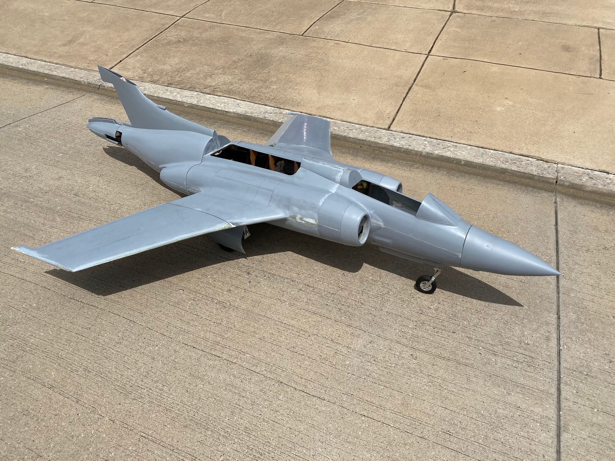
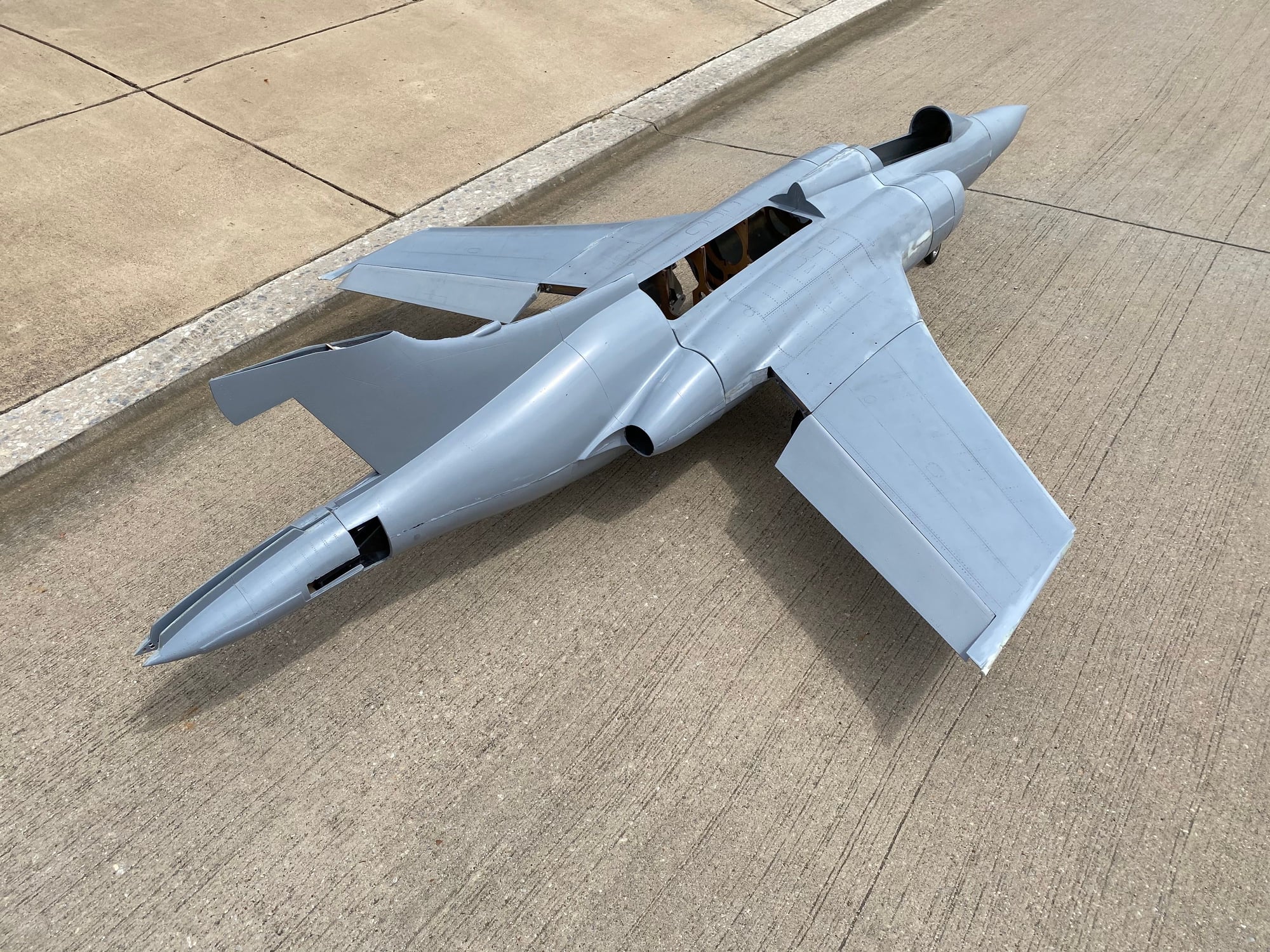
I finally finished the rear fuselage. While i was waiting for some servo arms so that I could get some measurements to allow me to finish the rear fuselage internal structure I remade the forward fuselage.
I was never happy with the first forward fuselage, and this next one came out much better. I also tried a lighter layup, veil+3oz+9oz, plus reduces some of the internal wood structure. It saved 6oz compared to the first one.
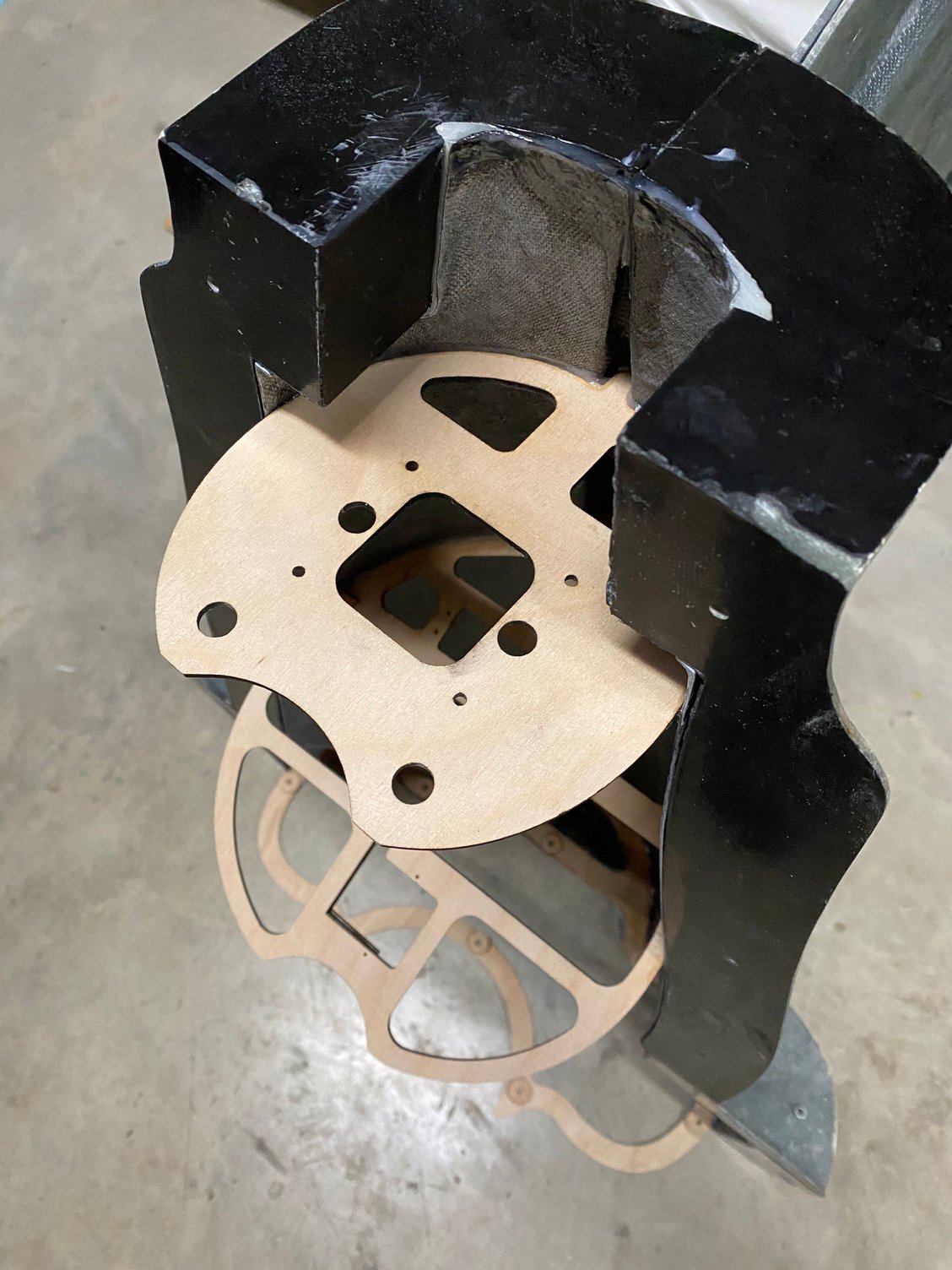
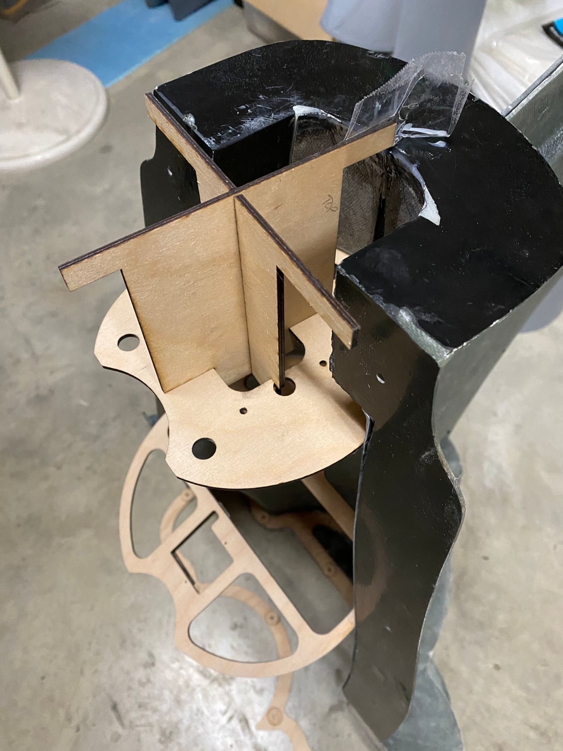
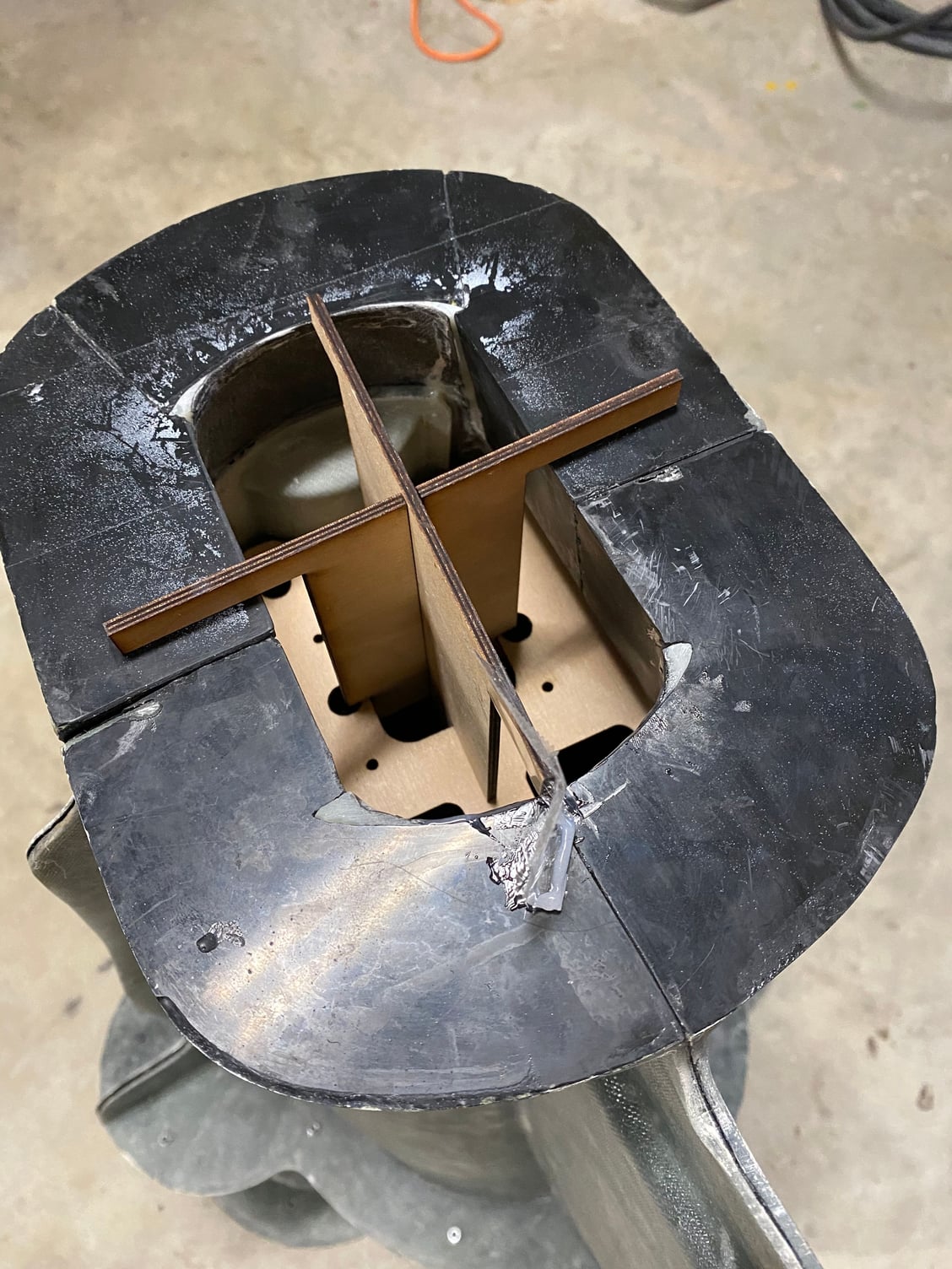
I assembled the rear fuselage in 2 stages, first bonding the internal structure and the 2 upper sides together. I then had relatively good access to tape up the seam before joining the lower surface.I made a jig to align the rear former as this is the mounting point for the speedbrake. A simple interlocking jig that aligns with the rear of the mold and it just twists 45deg to remove.
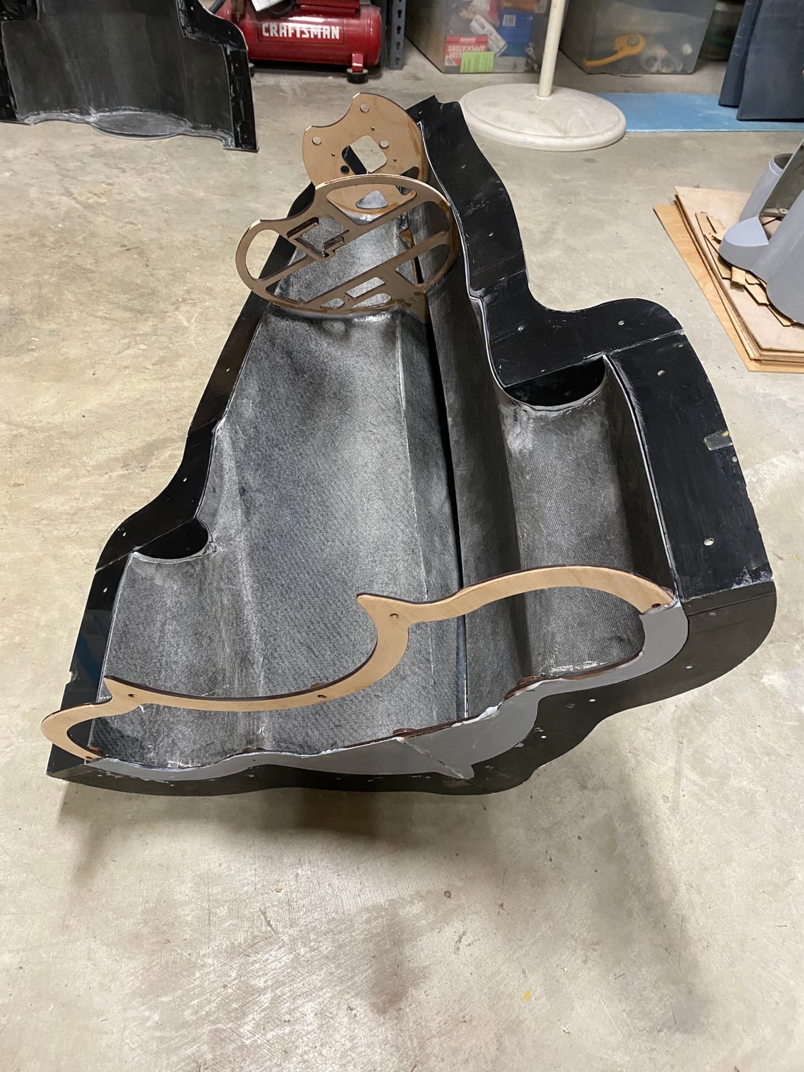
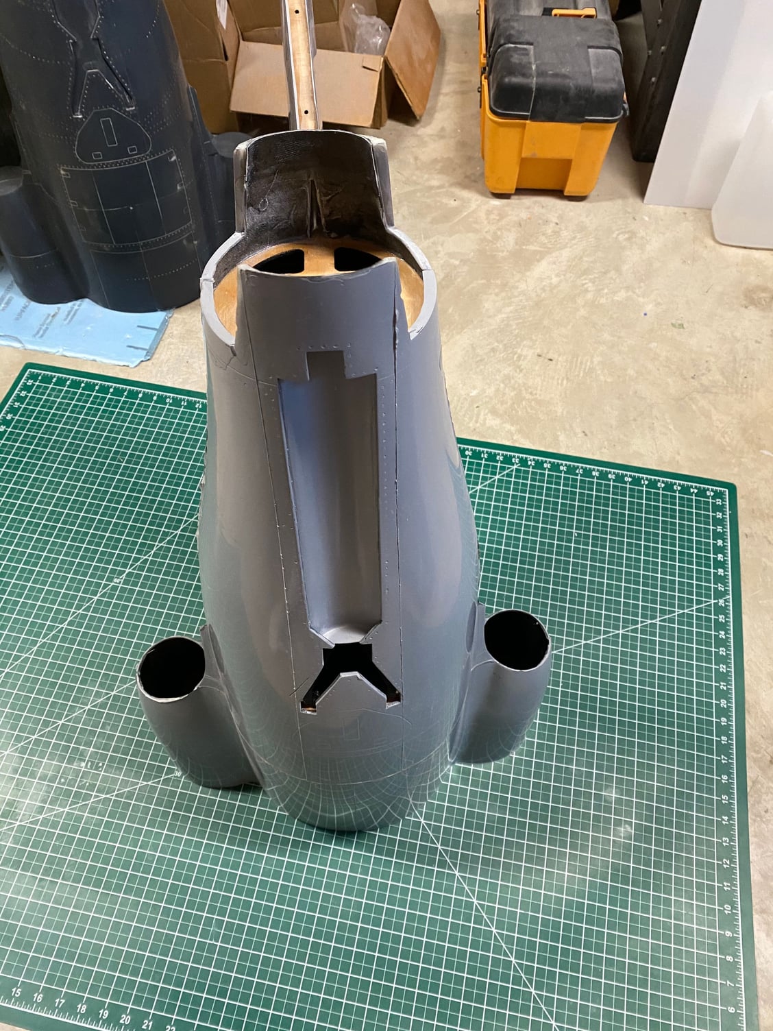
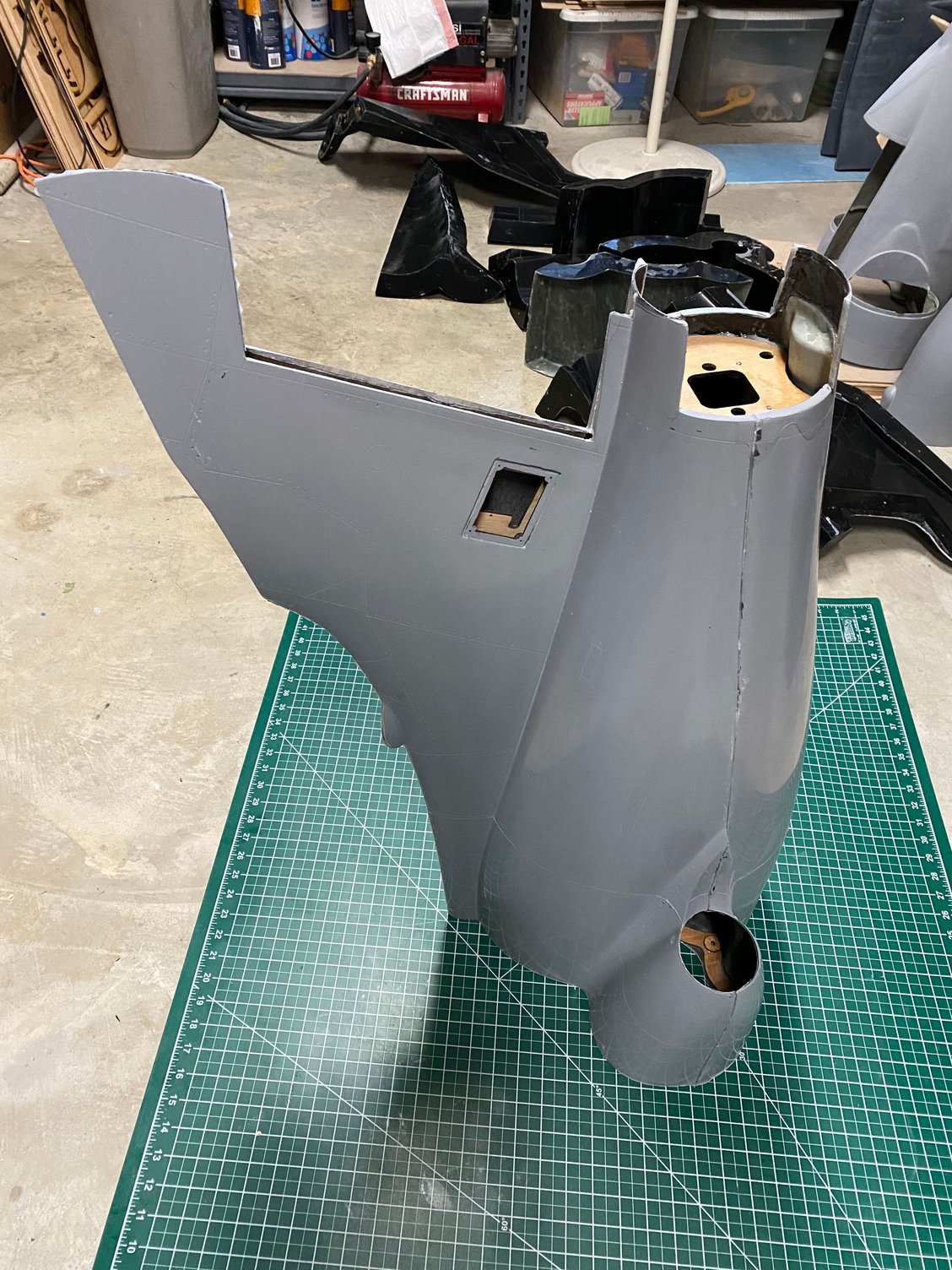
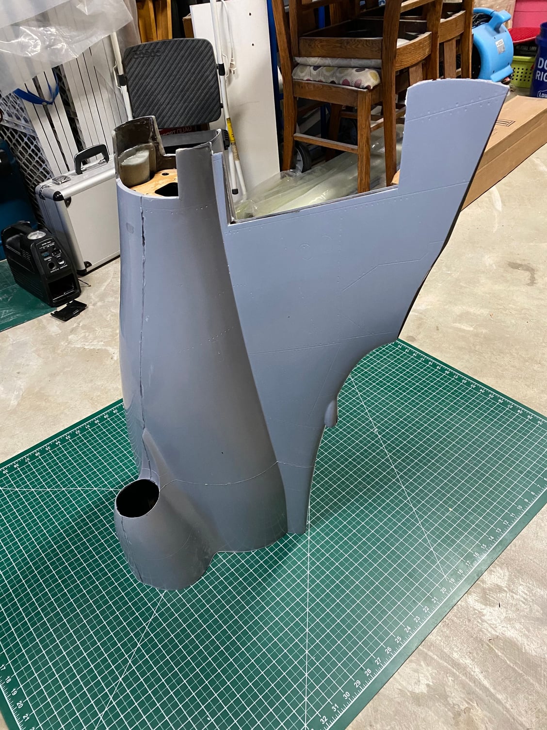
Paul
I was never happy with the first forward fuselage, and this next one came out much better. I also tried a lighter layup, veil+3oz+9oz, plus reduces some of the internal wood structure. It saved 6oz compared to the first one.
I assembled the rear fuselage in 2 stages, first bonding the internal structure and the 2 upper sides together. I then had relatively good access to tape up the seam before joining the lower surface.I made a jig to align the rear former as this is the mounting point for the speedbrake. A simple interlocking jig that aligns with the rear of the mold and it just twists 45deg to remove.
Paul


 07-04-2020, 03:39 AM
#446
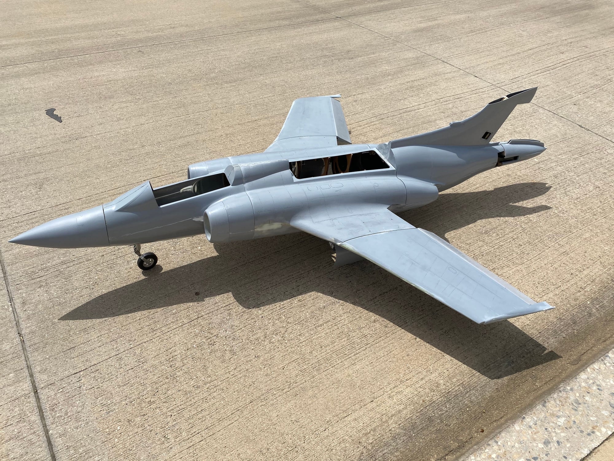
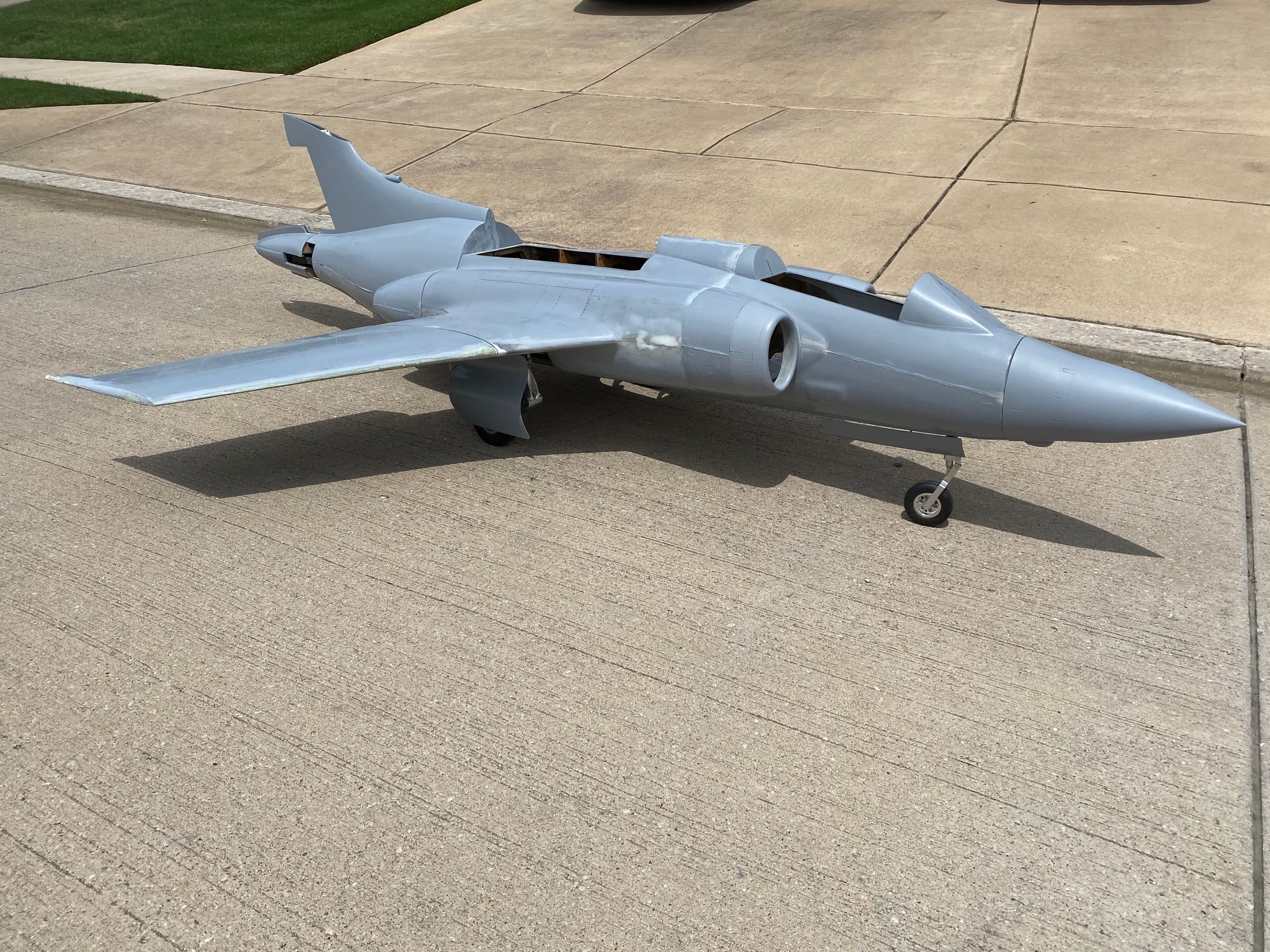
Hello Paul,
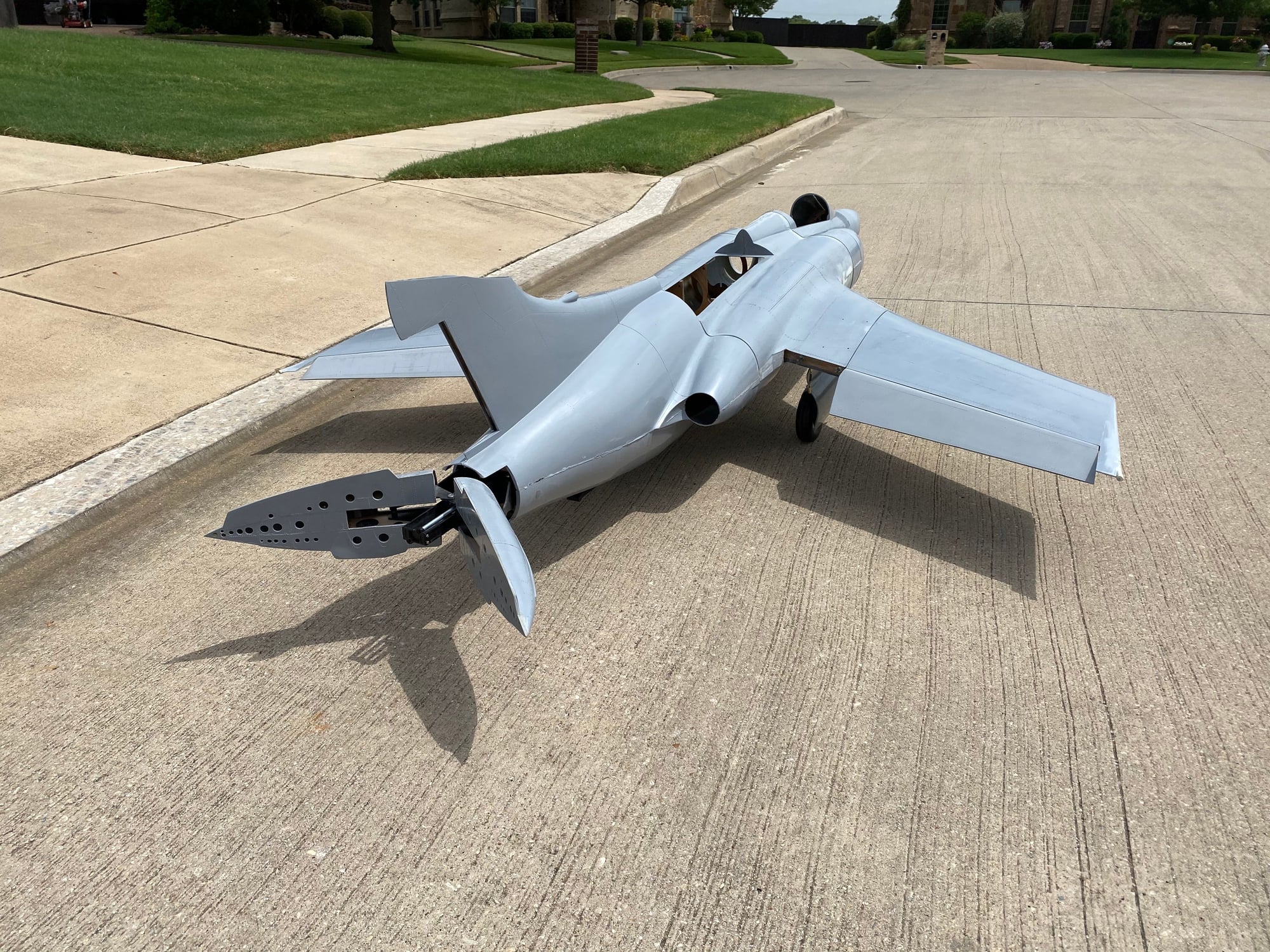
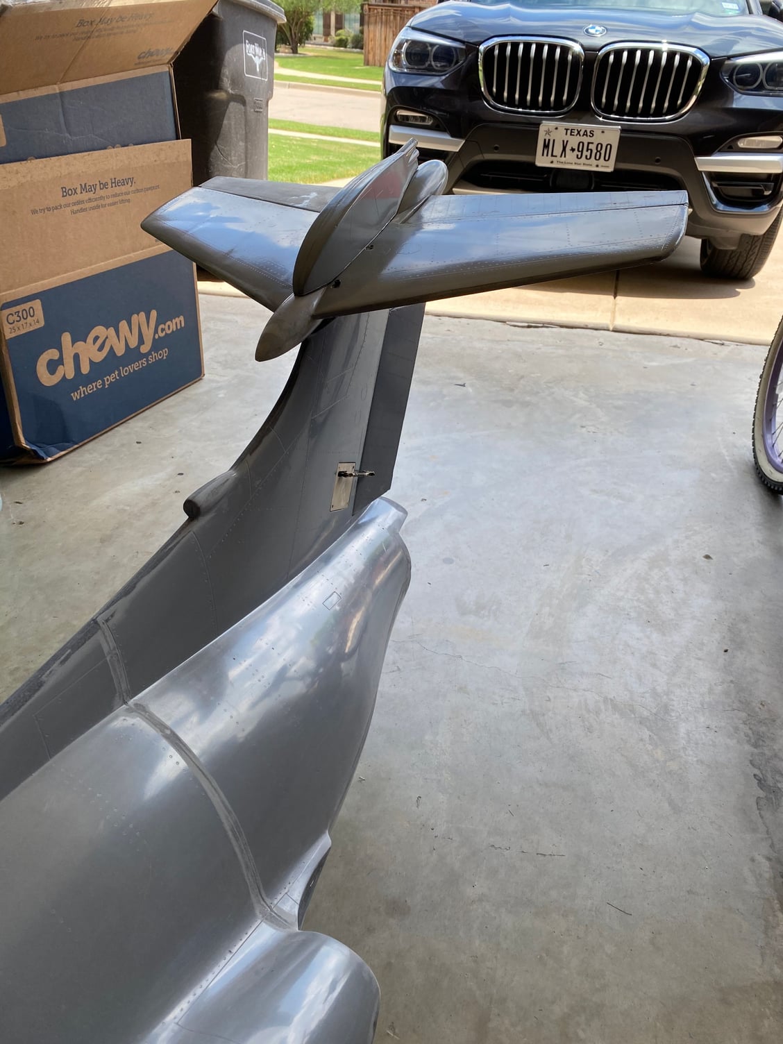
This has been an exciting project from the very start. Congrats on your progress, the jet looks fantastic on your driveway!
The jet should provide you with years of scale like dependable service.
Look forward to all of your test flight work-ups.
Franko
This has been an exciting project from the very start. Congrats on your progress, the jet looks fantastic on your driveway!
The jet should provide you with years of scale like dependable service.
Look forward to all of your test flight work-ups.
Franko
08-15-2020, 12:43 PM
#447
Feels like a while since the last update. Been working on various fronts, but not a whole lot of really visible progress. Here's the last months' work in an approximately chronological order.
Attaching the main gear door drive links. I laser cut the mounting brackets for the door end out of 2mm G10, along with a simple alignment tool that would set the spacing of the drive bracket relative to the hinge line. After Dremeling out the slot in the door, the drive brackets were Hysol'd in place.Once cured, a function check allowed the rigging of the drive rod to be adjusted and both door were confirmed to work well. Another triumph for the proceeding CAD work to confirm the geometry.
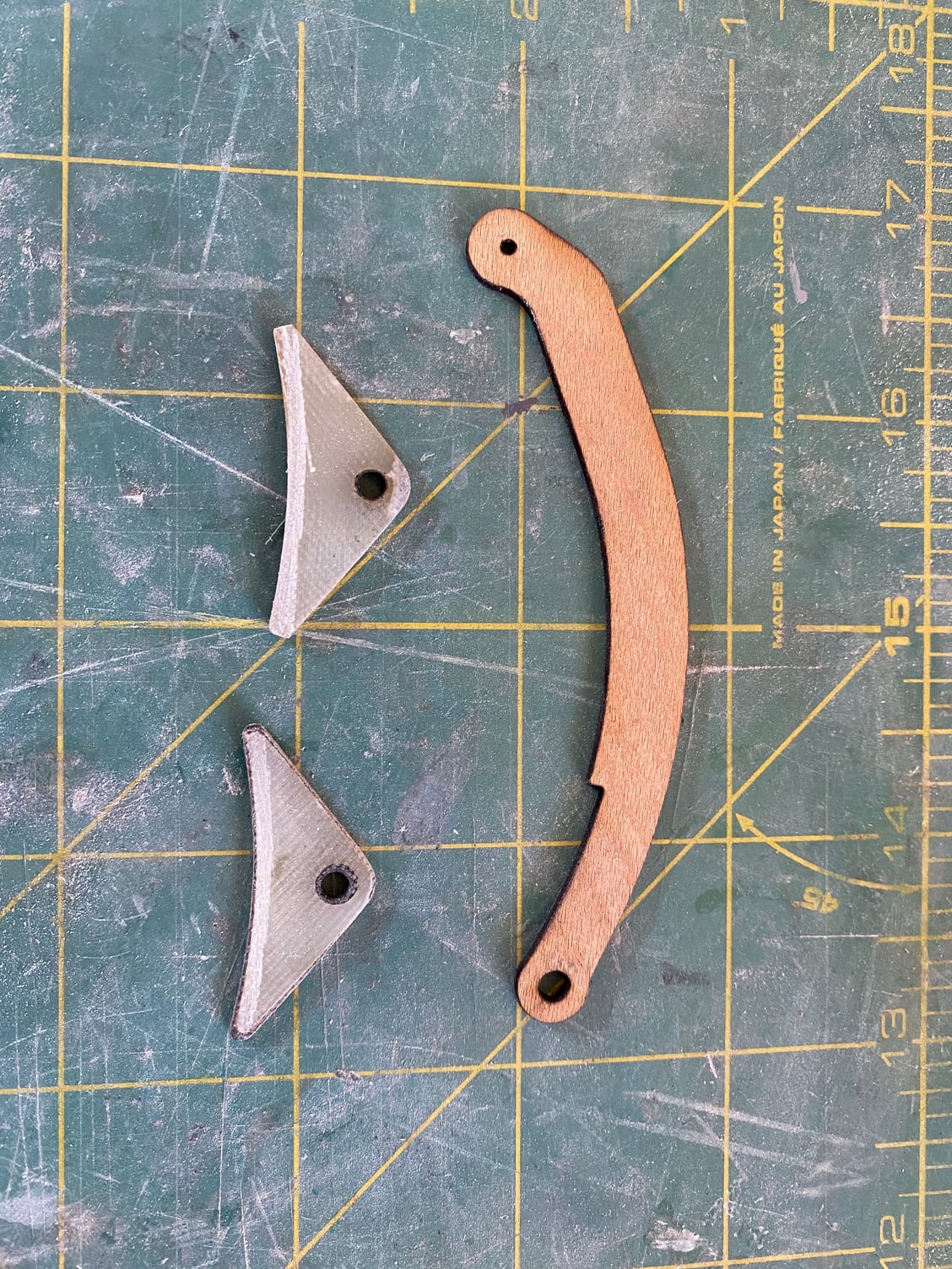
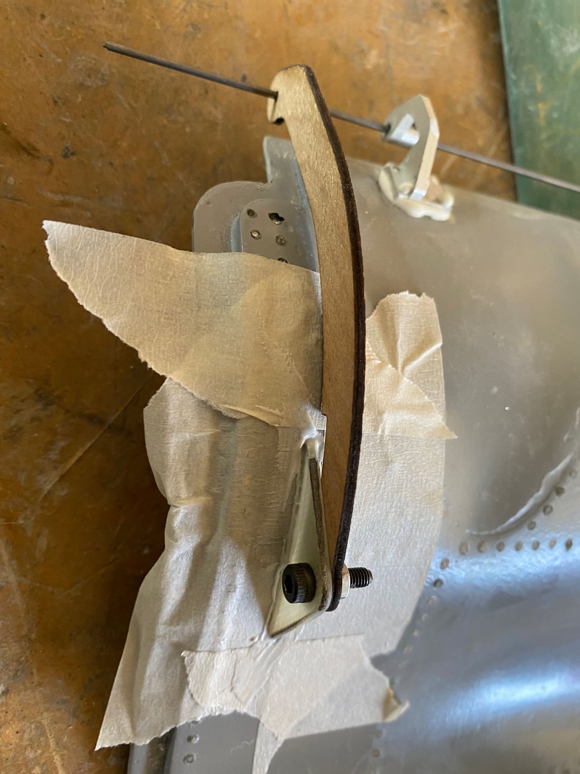
Attaching the main gear door drive links. I laser cut the mounting brackets for the door end out of 2mm G10, along with a simple alignment tool that would set the spacing of the drive bracket relative to the hinge line. After Dremeling out the slot in the door, the drive brackets were Hysol'd in place.Once cured, a function check allowed the rigging of the drive rod to be adjusted and both door were confirmed to work well. Another triumph for the proceeding CAD work to confirm the geometry.
08-15-2020, 12:48 PM
#448
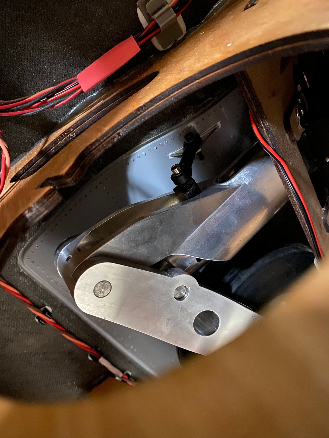
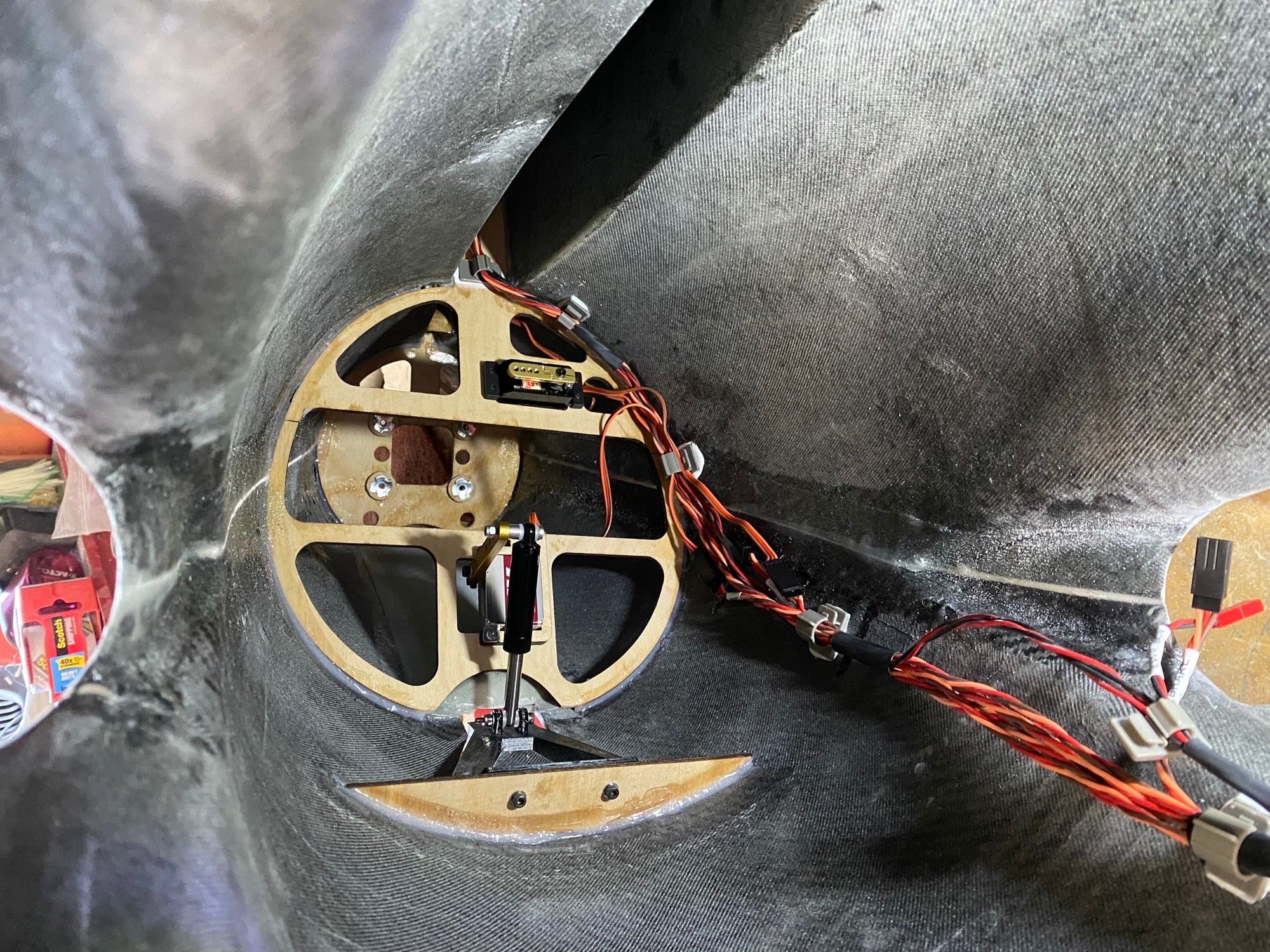
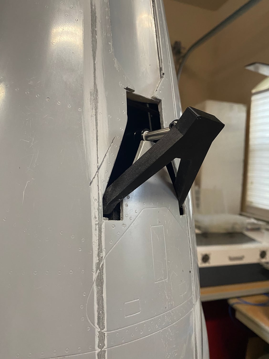
Next up was the retractable tail skid. The skid itself was 3D printed and can be easily replaced if it gets worn. I might add a metal skid plate to the end if it gets repeatedly scraped. A RC buggy shock absorber was used as part of the drive to protect the servo from shock loads. This servo will be tied into the gear doors via the Electron gear control box. The mount for this servo, and the main elevator servo was built into the main rear fuselage frame and fin spar.
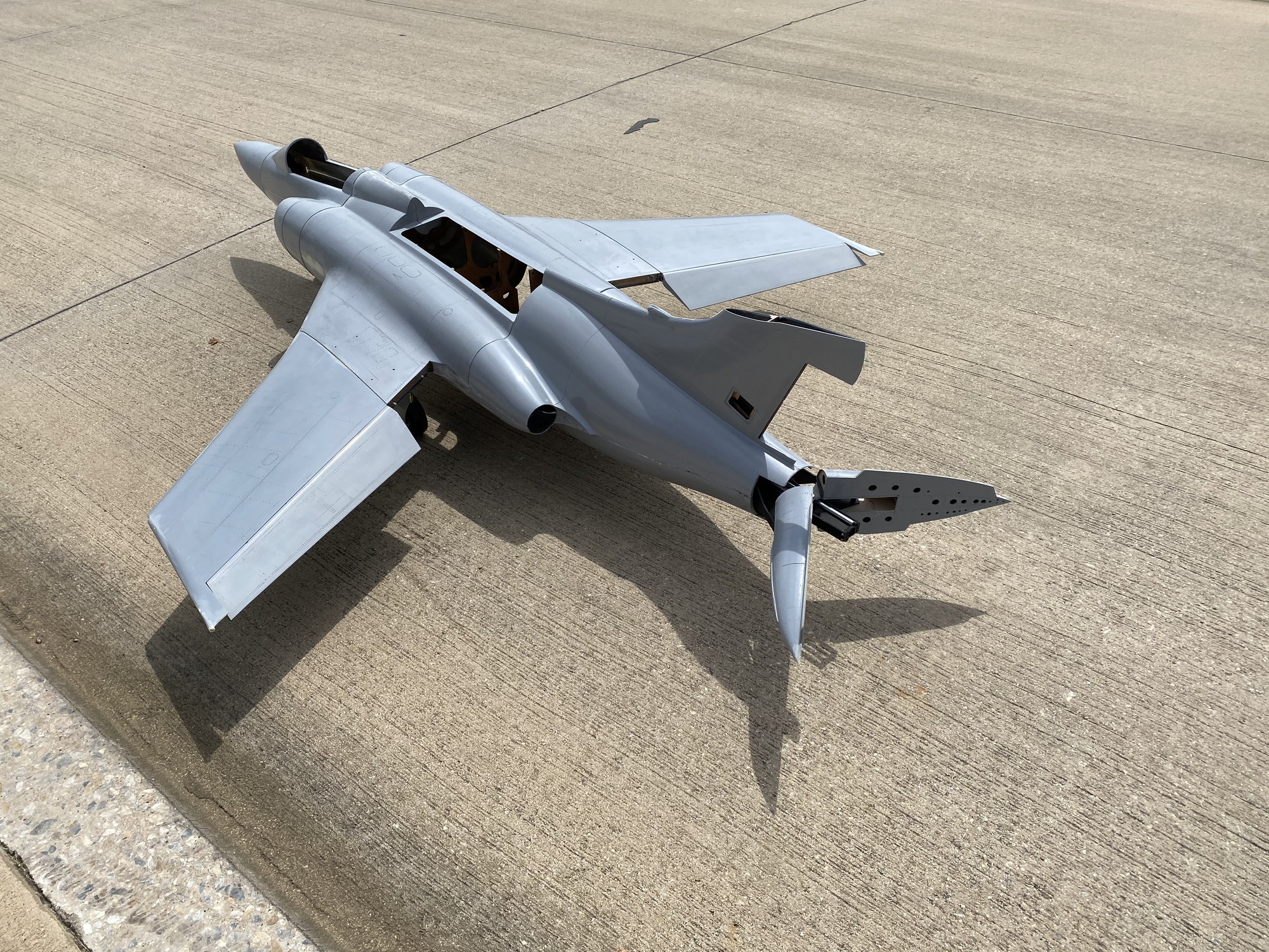
08-15-2020, 12:57 PM
#449
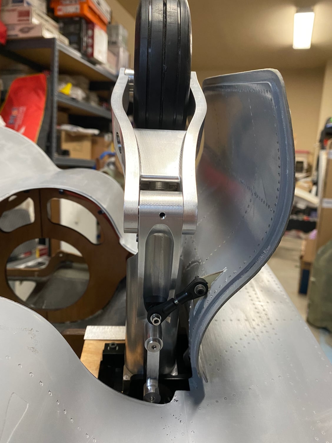
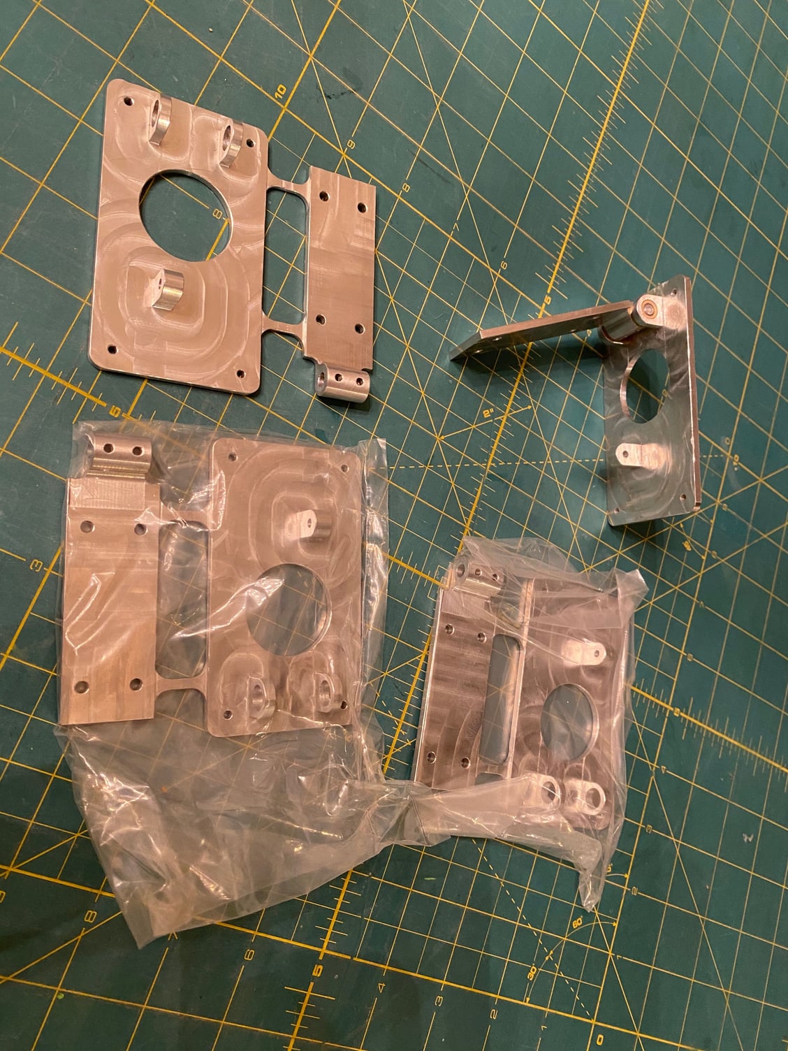
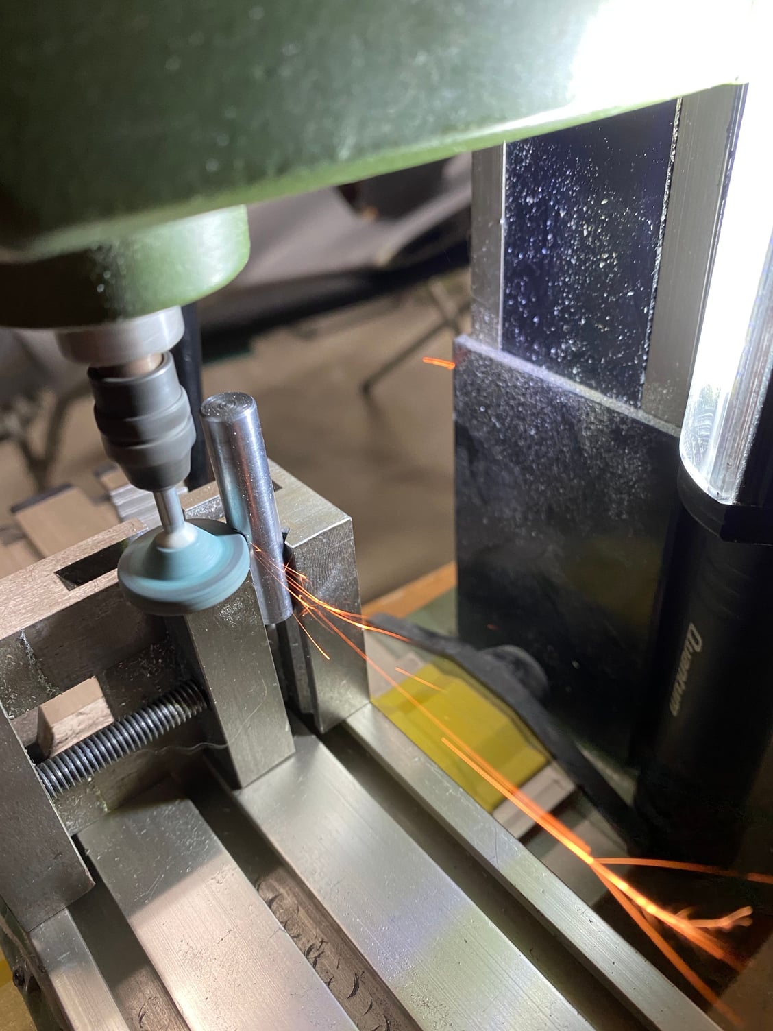
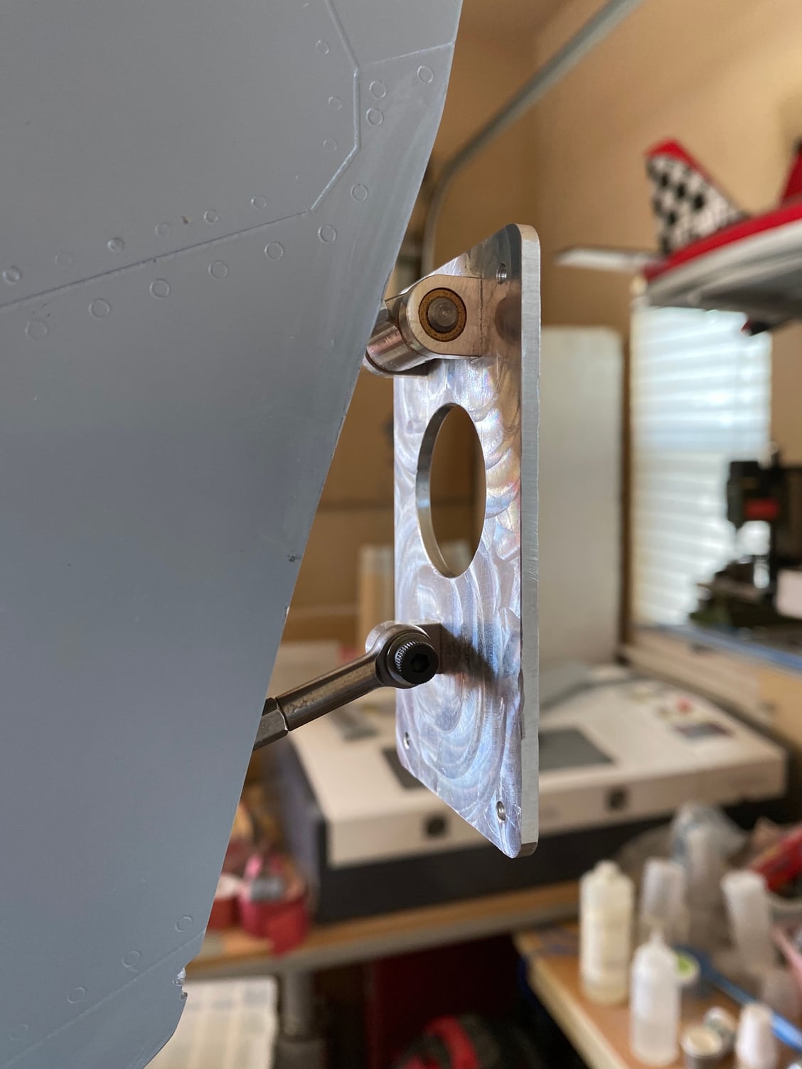
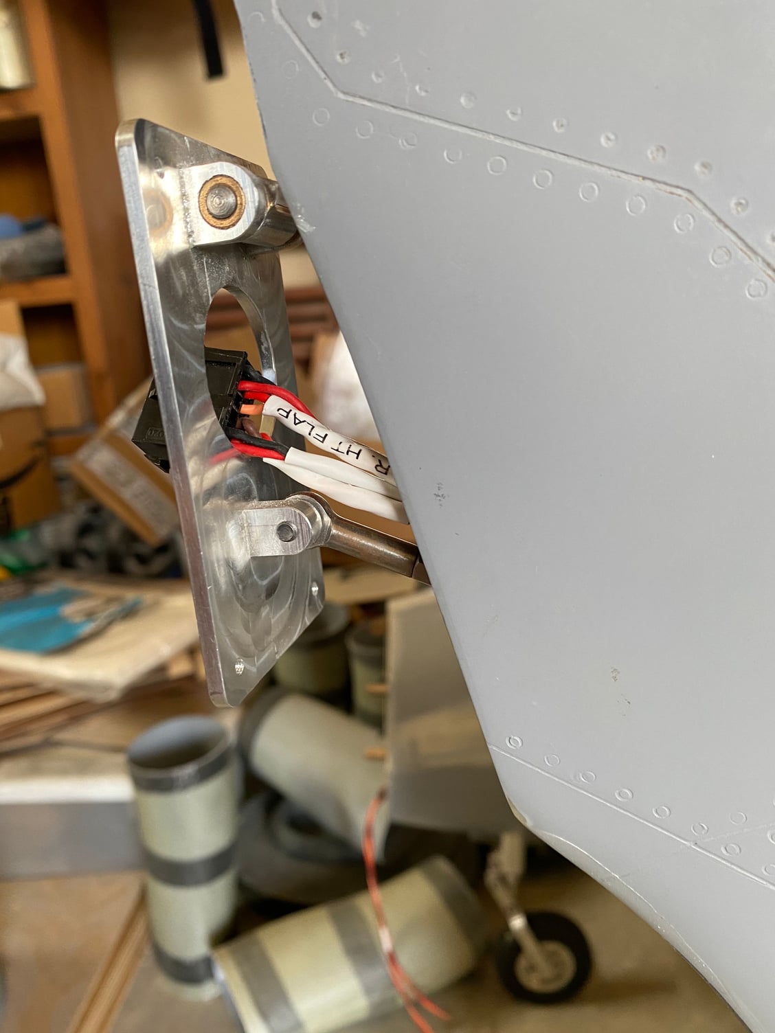
I had submitted what I hope to be the final machining order to emachineshop.com for the tailplane mount/ pivot. Machined out of Al 7075, and submitted as a single machining item with the 2 parts joined on a sprue reduced the cost compared to 2 separate items. I ordered 4 of them just to spread the set-up costs over them to make the unit costs a bit more reasonable.
After trimming the 2 parts and reaming the main pivot, Oilite bearings were Loctited in place. Flat spots were ground onto the pivot shaft for the retaining screws.
Trimming the previously completed tailplane and mounting the fin cap was a bit of a struggle, given that the fin penetrates into the tailplane and cap area. This one is a definite make-it-work solution, and I have plans to redo the tailplane assuming the model survives the initial flights.
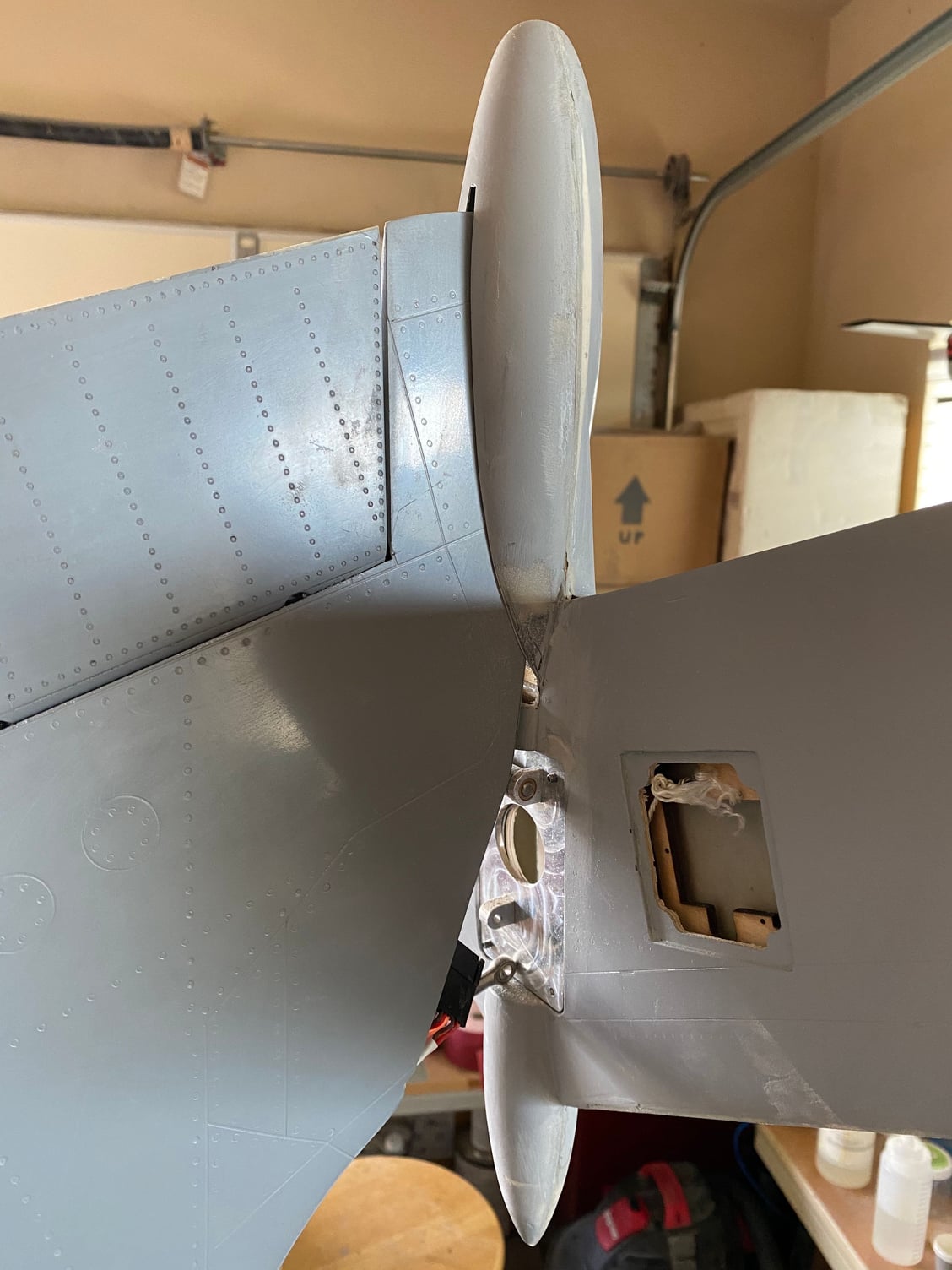
08-15-2020, 01:09 PM
#450
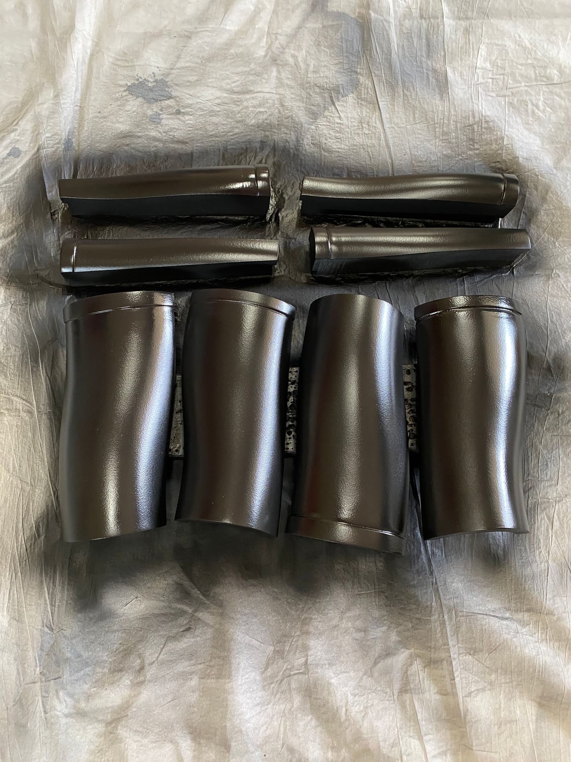
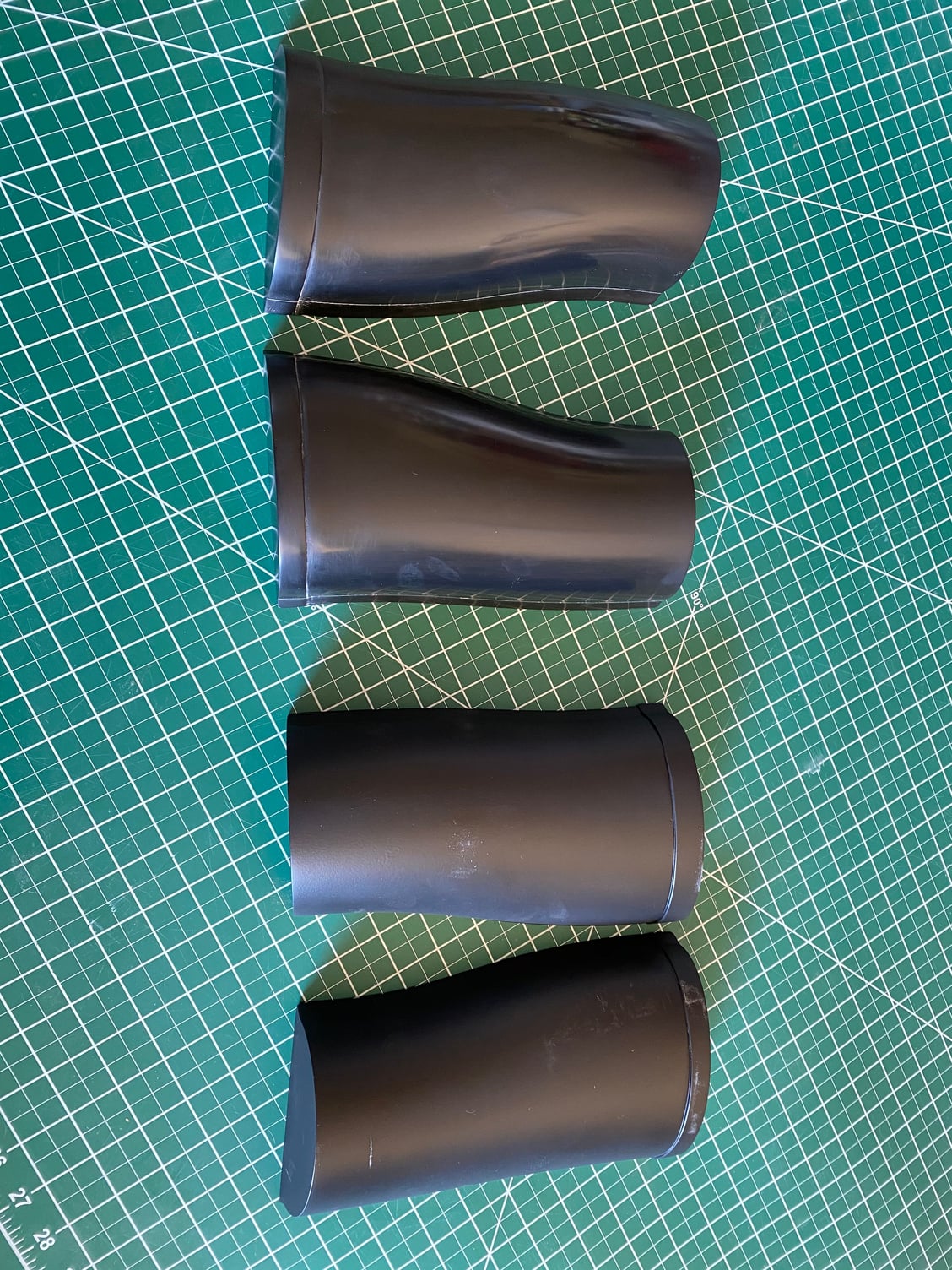
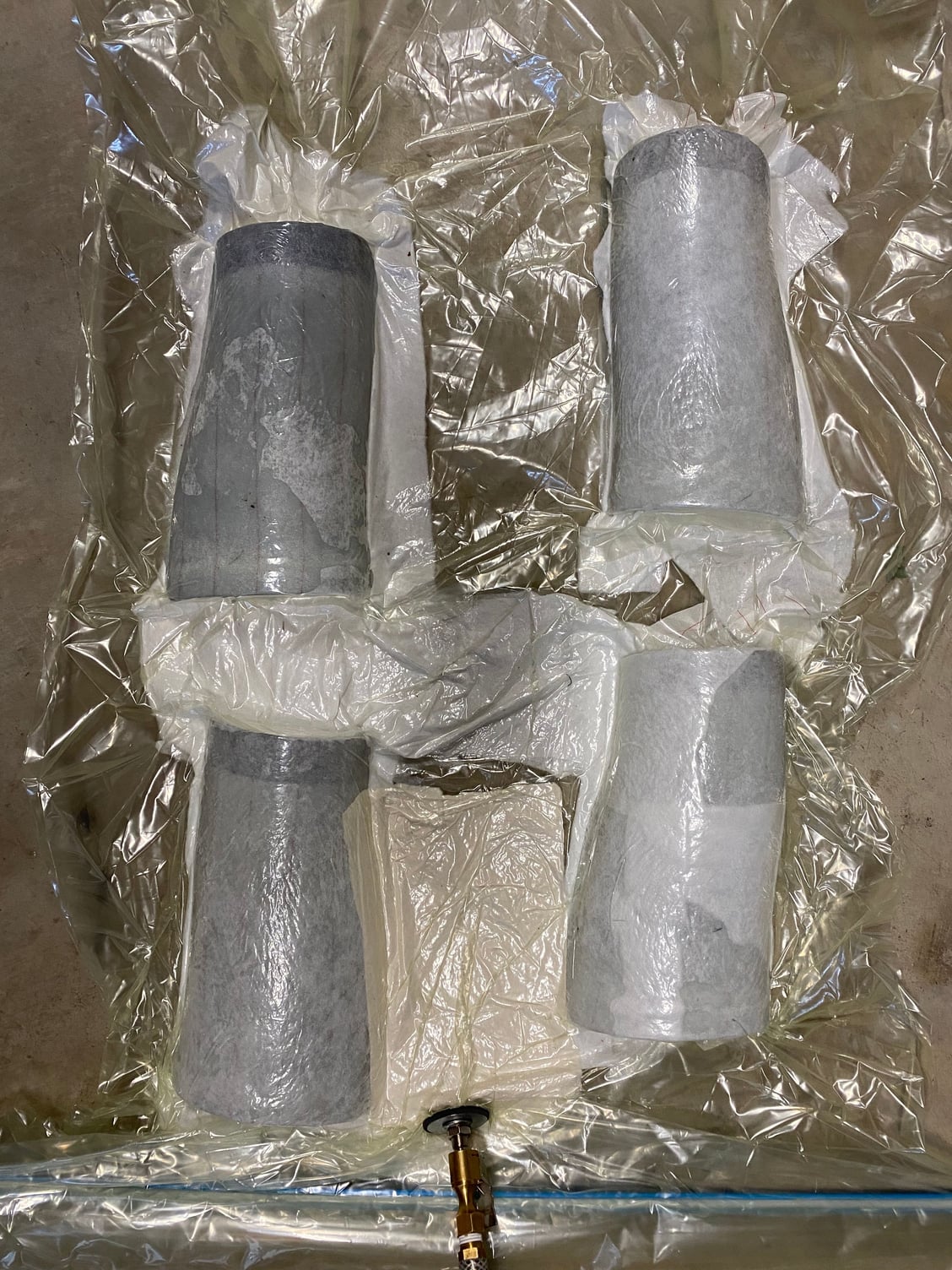
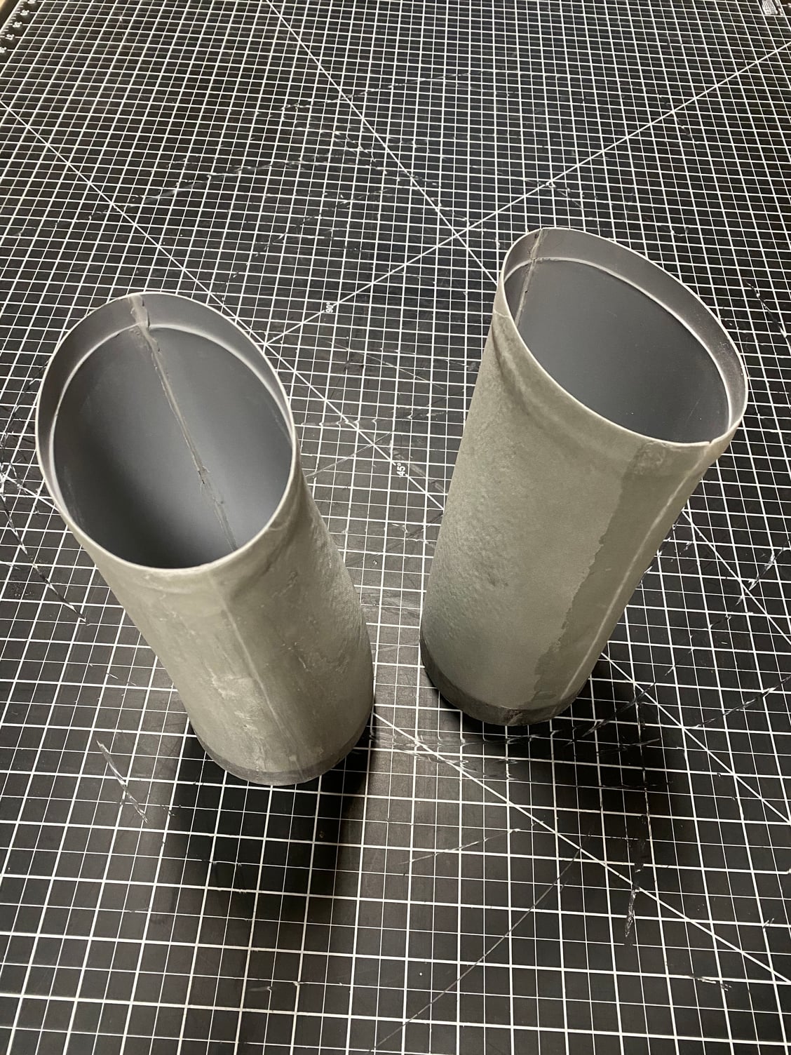
One area that I had not been happy with were the inlet ducts.Whilst the duct inner surfaces were fine, the glass came out all wrinkly when the vacuum bagging were I had tried to make the ducts in a single piece. The second pair I tried were not vacuum bagged and were around 50% heavier due to the excess resin not being removed. I also damaged the mandrels with this second pair so this was an opportunity to start again.
The second set of mandrels were made with a adequate draft angles allowing them to separate as they were taken apart. I had a different molding approach in mind, rather than using the vacuum bad, I tried wrapping the layup with Stretchlon bagging film, but that didn't work out as I couldn't get a good seal. This one (#5) also came our wrinkled, but again usable if I had to.
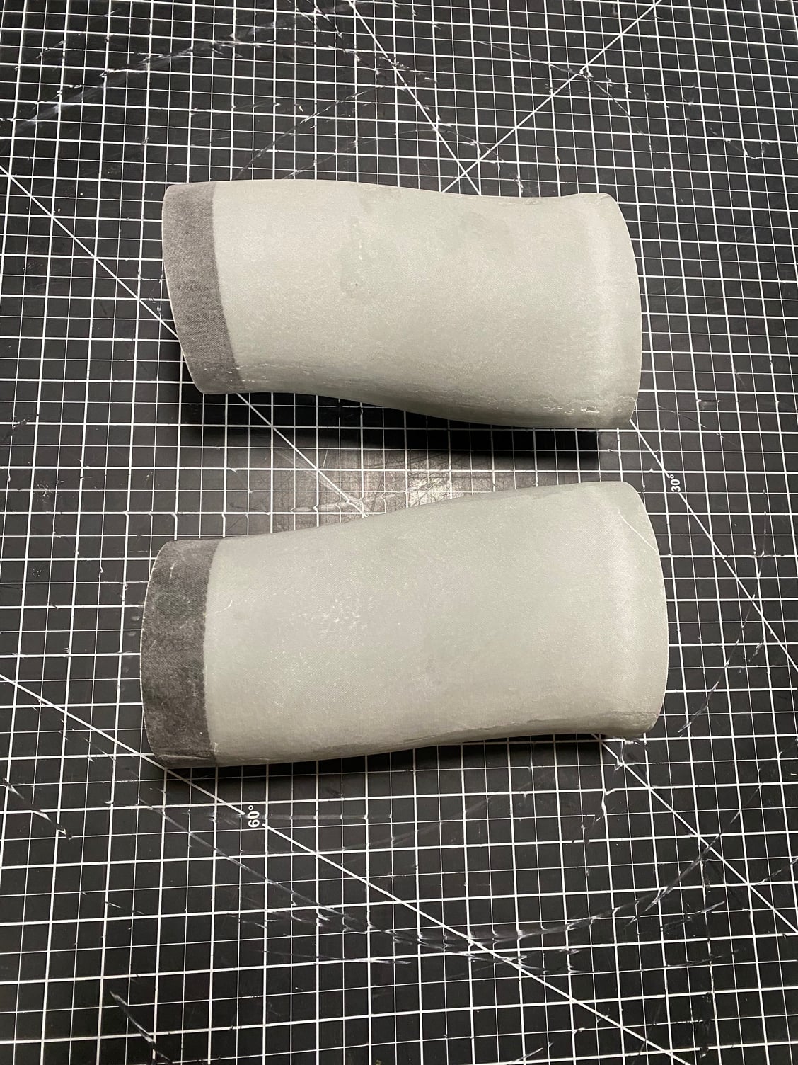
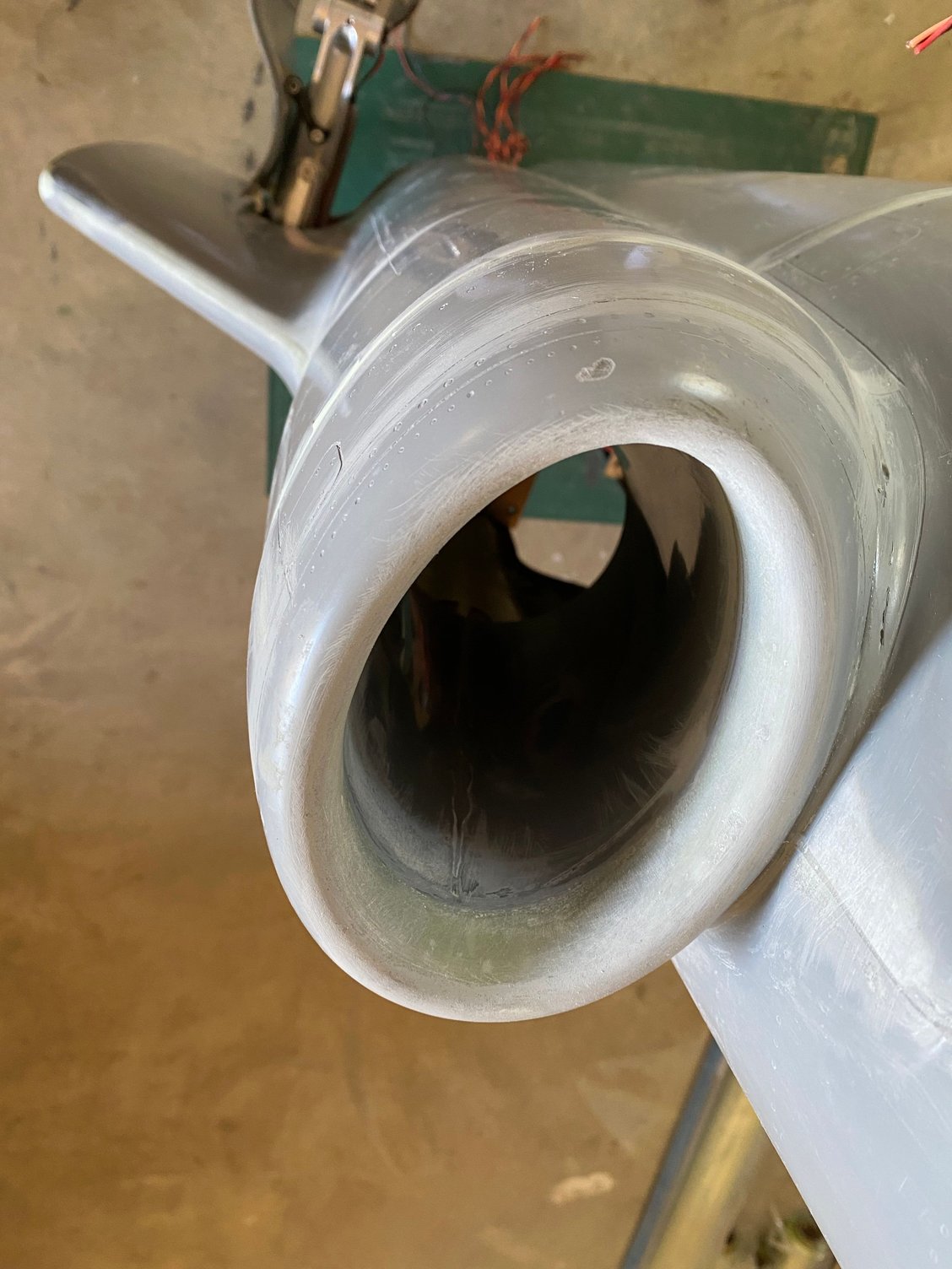
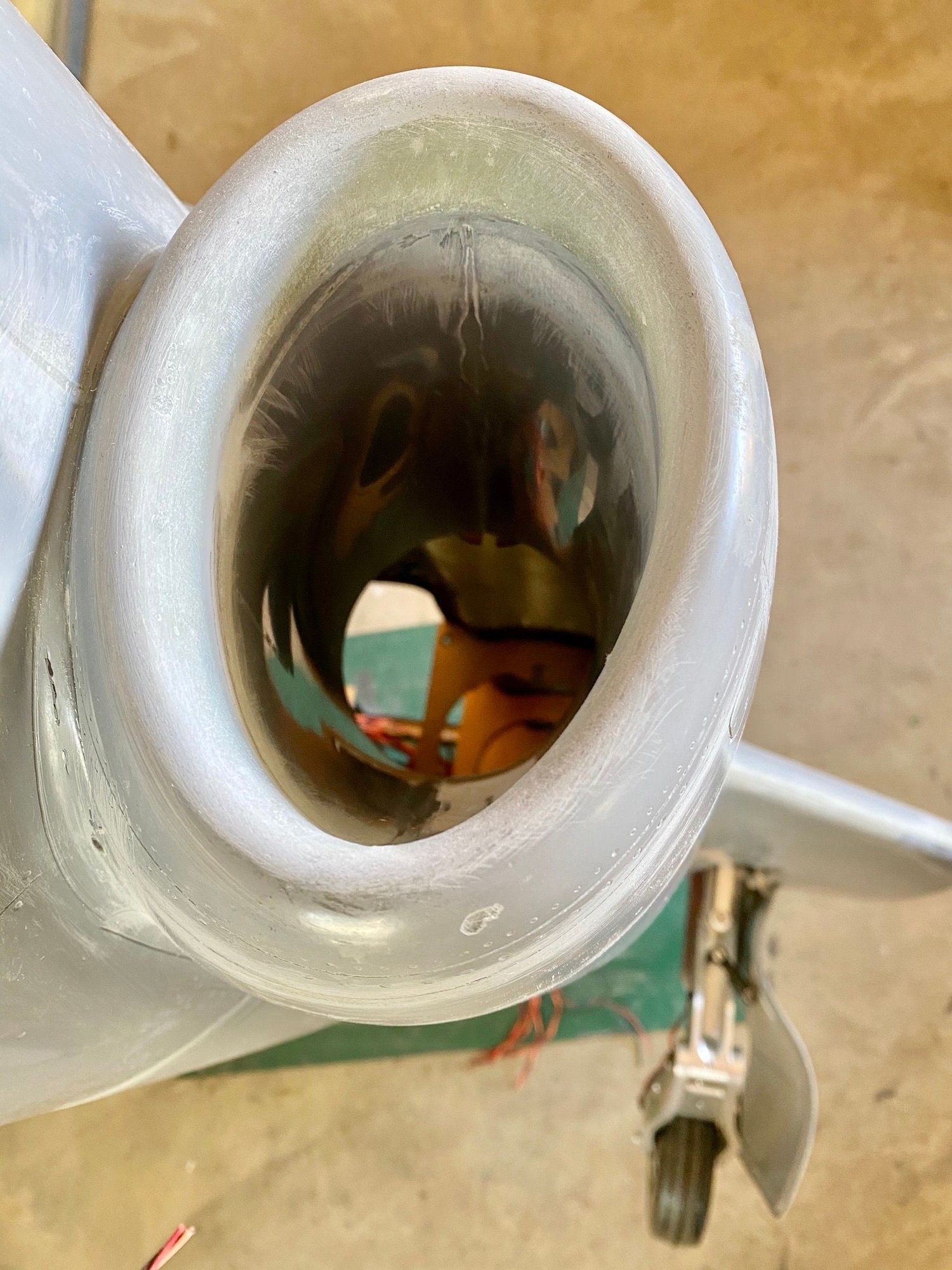
At this point, I decided to make more traditional inlet 1/2 molds an then join the two pieces afterwards. I 3D printed the 4 1/2 mold segments, glassed them and finished with Duratec. These pieces came out well, and I used the mandrels as an alignment fixture to join the halves together, so they were not wasted. Finally a decent pair of inlets that I bonded into the forward fuselage and blended the join with the inlets.
Those inlets were harder than they looked, but it was a valuable learning process.
The second set of mandrels were made with a adequate draft angles allowing them to separate as they were taken apart. I had a different molding approach in mind, rather than using the vacuum bad, I tried wrapping the layup with Stretchlon bagging film, but that didn't work out as I couldn't get a good seal. This one (#5) also came our wrinkled, but again usable if I had to.
At this point, I decided to make more traditional inlet 1/2 molds an then join the two pieces afterwards. I 3D printed the 4 1/2 mold segments, glassed them and finished with Duratec. These pieces came out well, and I used the mandrels as an alignment fixture to join the halves together, so they were not wasted. Finally a decent pair of inlets that I bonded into the forward fuselage and blended the join with the inlets.
Those inlets were harder than they looked, but it was a valuable learning process.