


Tony Nijhuis Vulcan bomber
 01-04-2018, 10:06 PM
#101

Join Date: Mar 2007
Location: BiggleswadeBeds, UNITED KINGDOM
Posts: 35
Likes: 0
Received 1 Like
on
1 Post
Hi Dave,
thanks for the information as I was thinking of using the same retracts as I have experienced problems with all electric retracts. My Vulcan build is coming along slowly. Most of the woodwork is done, just the fin to go. Reckon it will be at least another year till it's done.
Regards
John
thanks for the information as I was thinking of using the same retracts as I have experienced problems with all electric retracts. My Vulcan build is coming along slowly. Most of the woodwork is done, just the fin to go. Reckon it will be at least another year till it's done.
Regards
John
 01-05-2018, 02:07 PM
#102
Hi John,
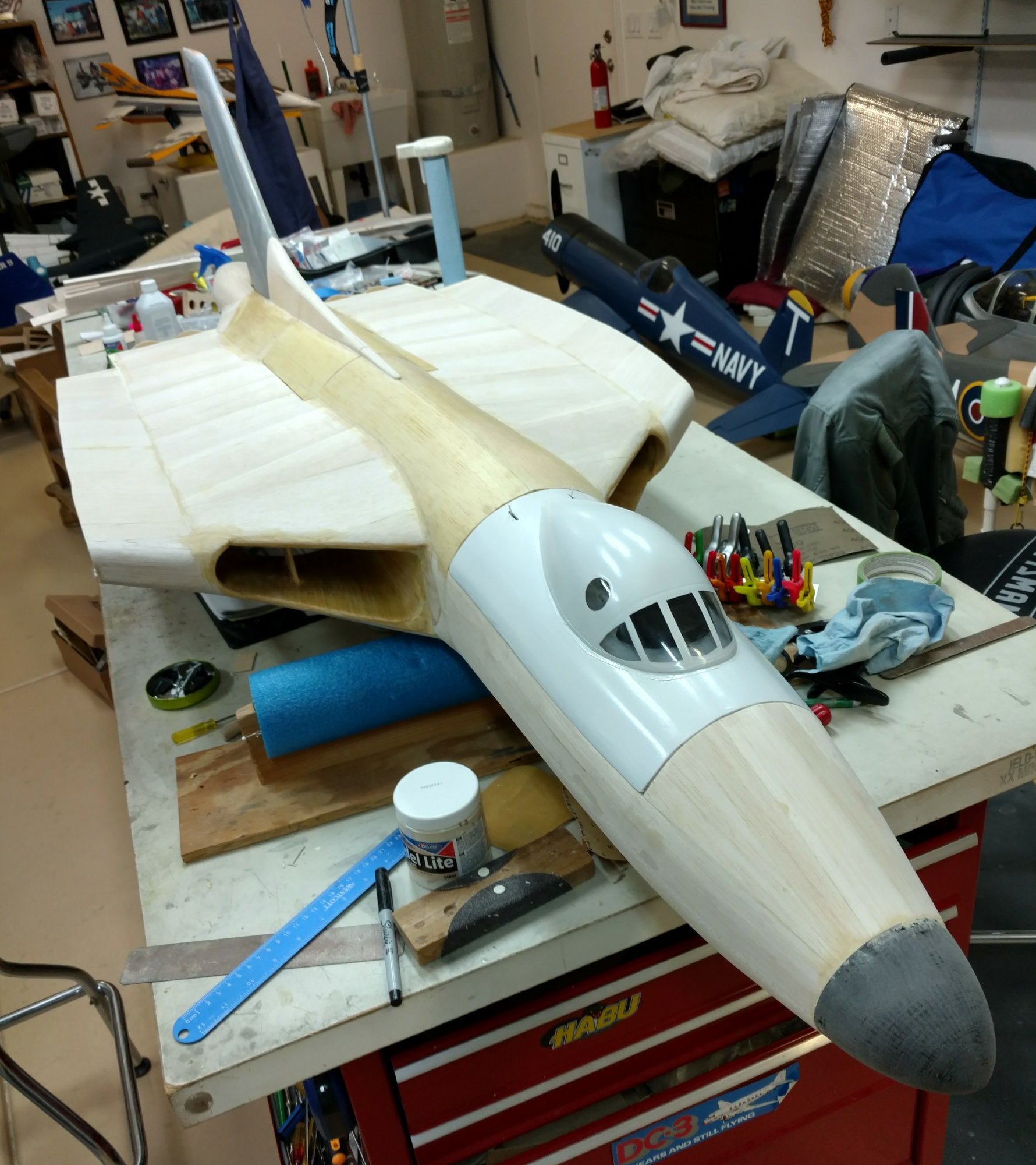
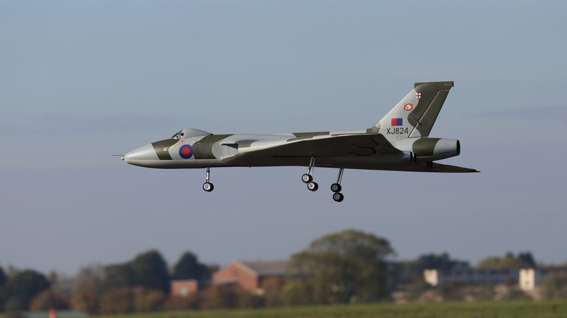
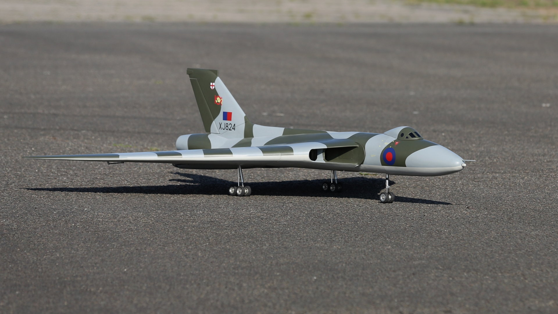
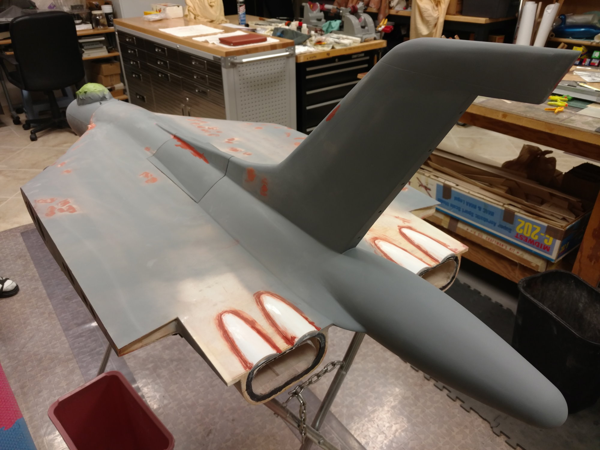
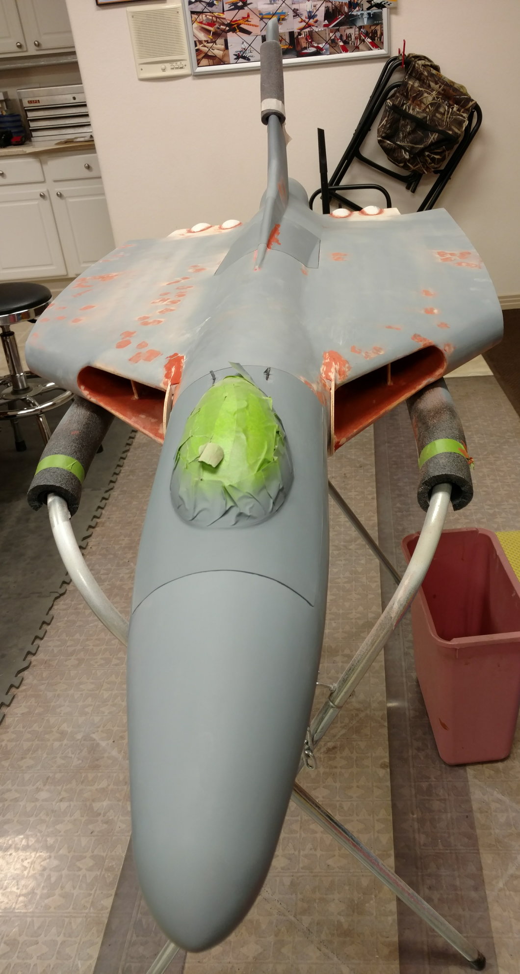
Wings and fin in primer, now back on with the fuzz! begin the build in December last year and hope to be flying in the summer. working on many fronts now, once the intakes are fitted and blended in, the fuzz will be ready for glassing.
Canopy is removable by pulling out the fuel probe (fitted after the photos) and reveals access to the sensor switch and the turbine i/o board so start should be easy on the flight line. nose removable (splits under the canopy) is bayonet mounted and comes off to reveal the batteries, radio, ECU and air trap/fuel pump.
Good luck with the fin!
roll on summer!
cheers
Dave
The following users liked this post:
Daveeast (09-01-2021)
 01-06-2018, 11:58 AM
#104
Join Date: Mar 2007
Location: BiggleswadeBeds, UNITED KINGDOM
Posts: 35
Likes: 0
Received 1 Like
on
1 Post
Hi Dave - saw your PM and replied. Vulcan looking very nice.
I'm not looking forward to all the glassing as never done it before. John R gave me some tips but I think I will start with the easy bits to gain confidence.
My plan for the install is to have a removable nose with a sliding radio tray which will have all of the switches mounted on.
Would be great to meet up and discuss the Vulcan. Perhaps we meet up in a convenient pub one evening?
Regards,
John
01-06-2018, 01:49 PM
#105
Hi All,
Capt G, Before building the nose, i made an identical former to F5. I'm sure the procedure would work for any model with a long nose that is built into the fuselage but it must not form a structural part of the fuselage. i placed the existing former on top of a piece of 6mm ply on the rotary table of my milling machine with the former as true as possible. 4 holes were drilled 90 degrees apart through both pieces of wood. this is the position of the bolts in the fuselage and the 'stop' point of the nose mounting. i then removed the existing former and drilled holes for the capscrew heads a few degrees back, can't remember how many now but it doesn't matter as long as they are all the same. after drilling the first head hole, rotating the table 90 degrees each time ensured the head holes were all the same distance away from the 'stop' holes. it was then a question of milling away between the holes taking care not to touch the back of the 'stop' hole. this produced 4 curved 'keyholes' in the new former.
attention now turned to the existing former. The cap screws were assembled temporarily with nuts each side just to check that the heads all lines up ok. they did so i 'wicked' thin cyno into the keyholes to toughen them up against the sliding of the cap screws in them. i used 5mm capscrews with a plain shank under the head so that the thread would not touch the keyhole. the cyno caused the wood to swell a bit so a bit of careful filing was called for!. once it all lined up, bolts were used to clamp the existing and new formers together in the fixed position and the outside of the new former was trimmed to the exact size of the existing one.
The bolts were held in the existing former by taking 4 pieces of hard wood and drilling a tapping hole for a 5mm thread but the holes were not tapped. instead i ran the bolts straight into the holes with an electric screwdriver. This makes a very tight thread so the bolts can be adjusted to hold the new former 'snug' and they stay where you put them. the hardwood 'nuts' were epoxied behind the existing former. you can see a couple of the bolts in the photo of the SB intake being fitted.
the nose is held in place with a commercial hatch lock which drops into a hole once the nose is rotated to the final position.
i have not finished the cabin lock yet but the rear of the cabin will have 2 lugs on the rear like surfboard fins which will go into slots. the front will have a hardwood block which will drop through a hole and be fixed in place by a wire going onto a hole. the wire is routed via a snake to the fuel probe. this is made in 3 parts. the fixed tube and snake get epoxied into the nose. the sliding part has the wire epoxied into the rear and a threaded hole in the front. when pushed in, the threaded hole end is flush with the end of the fixed tube. the probe has a thread (long setscrew) protruding from it so it can be removed for transport. hope the photos tell the story, any questions I'm happy to answer.
John, thanks! this was my first attempt at glassing but after a few hiccups and lessons learned it really is quite straight forward. Would like to meet up for a chat sometime. send me a PM and we can arrange something. a beer and talking models, whats not to like!
cheers
Dave
01-06-2018, 02:04 PM
#106
One other thing. you will see in the photo of the fuel tube in the nose that the fuselage is in the background. I made another piece of ply with holes to take the heads of the capscrews. this pushes in place so that the fuselage can be stood on its nose without risking damage to the front face. very convenient for working on the rear of the fuselage as i am currently working on the dummy engines.
i have made a removable section which is mounted to the (very strong) front section of the fuselage above the nose leg and extends into the nose. this will carry all the batteries, ECU, fuel pump and gyro keeping the weight as far forward as possible but without any weight being carried on the nose cone.
Cheers
Dave
01-08-2018, 01:16 PM
#109
Capt G,
I have put off doing the canopy until the fuselage is glassed as the radius is going to change slightly. will post details as soon as i can. Are you building a Vulcan?
cheers
Dave
I have put off doing the canopy until the fuselage is glassed as the radius is going to change slightly. will post details as soon as i can. Are you building a Vulcan?
cheers
Dave
01-16-2018, 10:00 AM
#111
Join Date: Mar 2007
Location: BiggleswadeBeds, UNITED KINGDOM
Posts: 35
Likes: 0
Received 1 Like
on
1 Post
Hi Dave, John
Any chance you have kept the details of the rods and tubes you used to make the fin removable. I'm keen to do this modification.
Thanks
John
Well Done Capt G
Any chance you have kept the details of the rods and tubes you used to make the fin removable. I'm keen to do this modification.
Thanks
John
Well Done Capt G
01-17-2018, 02:39 PM
#112
Hi John,
post number 90 shows a couple of photos of my fin during building and I'm sure John R put a couple up somewhere The rods in the fin are 10mm OD carbon tubes. the tubes slide into 10mm ID ally tubes in the rear fin base. an extra couple of ribs were made for the split point in the fin and beneath the base one was filled with a balsa block into which the ally tubes were glued. the fin will have a lot of leverage on this block which is only supported by the turtle deck formers so i made a glass fibre front former with a tab that was glued to the front of the balsa block and 2 tabs that went through the top sheeting and down the sides of the inner 2 formers. A similar glass former was added to the rear of the block too. when the whole lot was epoxied into place (photo) it became very firm and so the forces on the fin are carried down into the 2 inner formers. the 2 carbon tubes must be kept parallel and were glued into the fin first. the ally tubes were later epoxied into oversize holes in the balsa block so they could self align and were held in place by the fin itself while it all dried. during drying, a diagonal rod was temporarily glued (with cyno) to the top of the fin and held with clamps to the side of the fuselage. This was adjusted to hold the fin dead square. a hole in the balsa block will allow the rudder servo cable through to the fin.
cheers
Dave
01-18-2018, 11:06 AM
#113
Join Date: Mar 2007
Location: BiggleswadeBeds, UNITED KINGDOM
Posts: 35
Likes: 0
Received 1 Like
on
1 Post
Thanks for the detailed description Dave. I like adding extra formers ant tieing them to the circular formers - I was concerned about the strength of the fin so that mod will help.
I'll look to source the aluminium and carbon tubes.
Kind regards,
John
I'll look to source the aluminium and carbon tubes.
Kind regards,
John
01-21-2018, 12:02 PM
#115
I have not quite got that far yet. i want to investigate sprung-open doors that are closed mechanically by the retracting leg rather than servo driven. main reason is that for transportation the gear will be up and the doors closed. when i take the fuselage out of the van, i want to be able to manually operate the gear servo and put the gear down without worrying about 'are the doors open'?
Nothing decided yet!
Nothing decided yet!
01-25-2018, 02:25 PM
#117
The plan shows self tapping screws which i didn't like the thought of. I have ended up with 2 borrowed ideas.
John R had the idea of fixing the main wing tube in the main fuzz by plugging the end of the tube with a machined plug having a central tapped hole. the inner end of the outer tube was fitted with an aluminium threaded plug into which a screw was stuck, protruding into the tube so the wing tube can be screwed into the fuzz and is held solid.
For the wing end i borrowed an idea from my Xcalibur jet. on this, the one piece wing tube is fixed each side by a clamp inside the wing and a small hole in the upper surface is all that is needed for a hex key to go through to tighten the clamp bolt. I have not seen inside the Xcalibur wing but deduced what must be in there.
I found a large cable clamp that was the right size for the wing tube and machined half the thickness out larger to fit on the end of the outer tube that is stuck in the wing. once fitted, i cross drilled the joint with tiny holes in several places so that when it was stuck, there would be little pins of glue that would stop it pulling off the end. i also put glue on the outside to help it, not too tidy but never seen. an 8mm carbon tube guides the hex key into the hole in the screw, sanded off level after glueing. Finally the 5mm nut used was a captive nut with spikes on. i drilled the plastic clamp to accept the spikes and glued it in with Loctite epoxy as the rest was stuck with. i didn't glue the complete diameter of the clamp so that part of it can move to actually clamp the tube. it is very solid. hopefully the pics will help.
Happy building!
 06-27-2018, 12:37 PM
#119
Hi Capt G,
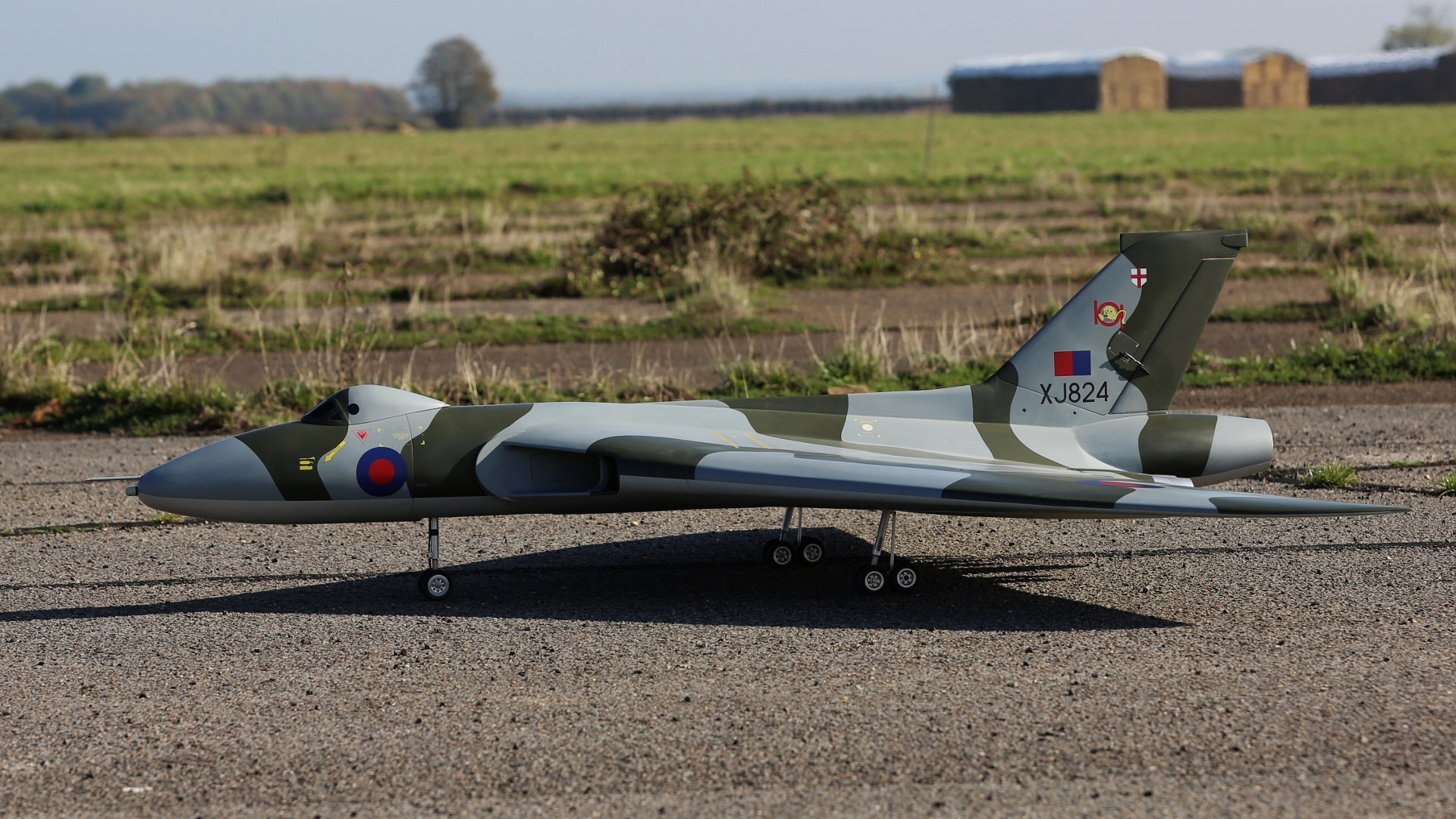
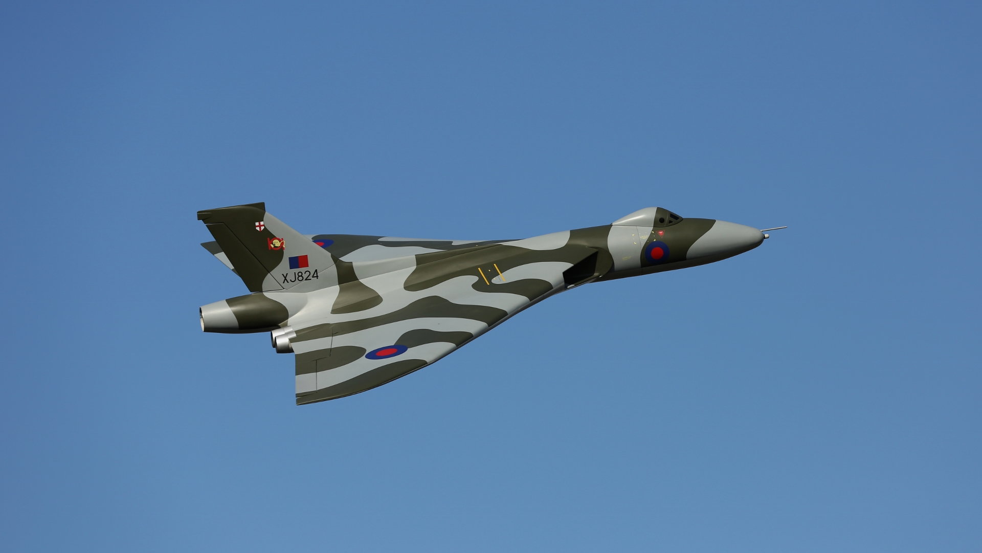
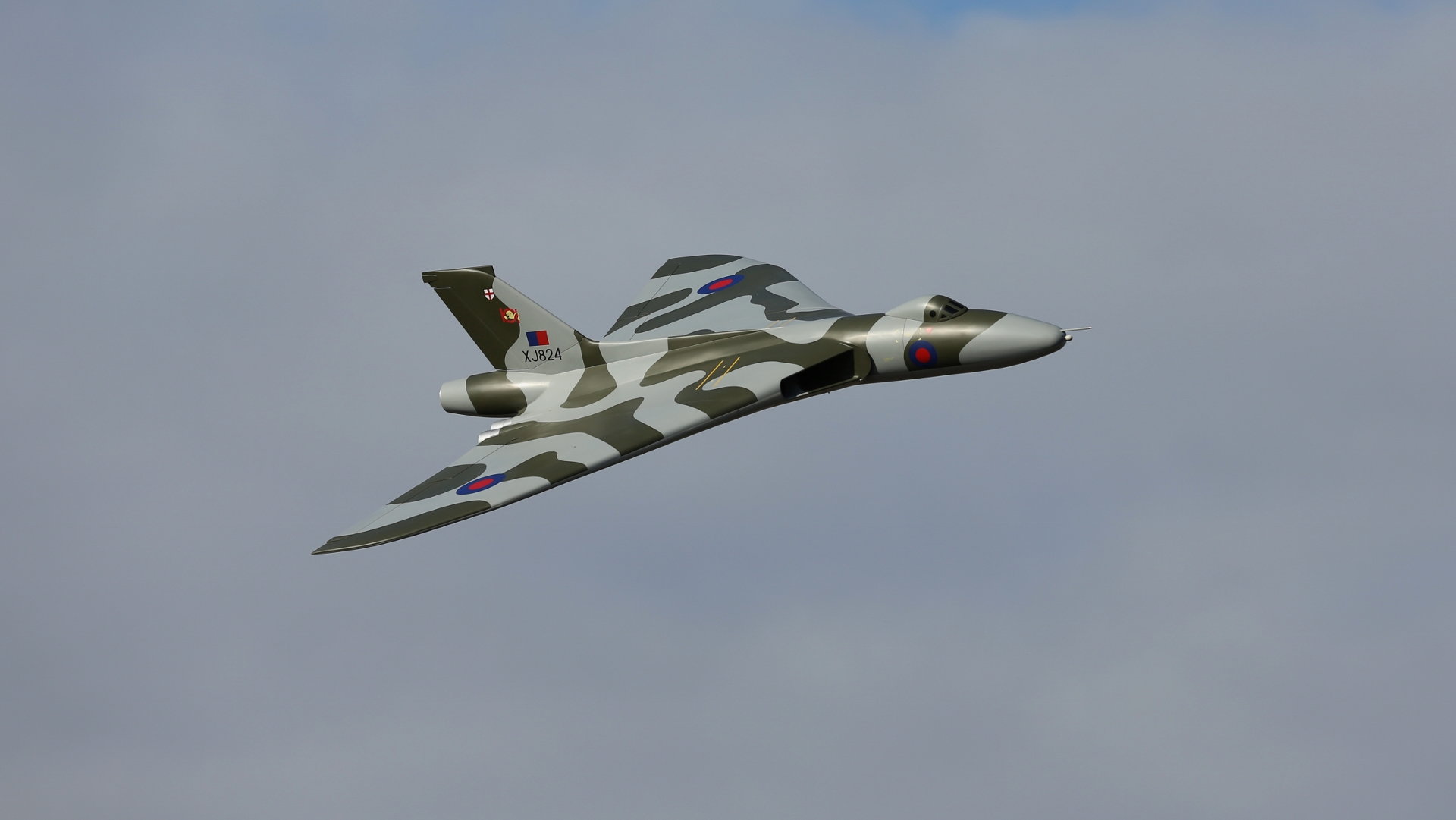
lots of progress but not posted anything for a while. The painting went well and can now start putting things in that can STAY in! I have fixed 6mm dowels front to back and side to side to carry all the cables and fuel lines, all wiring etc is not routed to the front where the radio/battery tray is mounted under the removable nose. I made another mod that I don't have photos of at the moment, it is an extension to the main wing spars to tie them together at the bottom. reason for this was that I made the turbine access a little larger than Tony says to get the P100 in and out easier and realised that the only thing stopping the wings 'clapping' during a high G pull is the wood above the main spars being compressed. this is a very weak area anyway so I added some aluminium bracing below the turbine which will be trying to be expanded during a high G pull up and should be much stronger.
I like your removable canopy for access to the inner workings. always more than one way to do things!
Good luck with the glassing, I really enjoyed it!
Her maiden is planned for Oct at a jet meet on a runway. gives me plenty of time I hope to get it finished.
The following users liked this post:
Daveeast (08-30-2021)
 10-23-2018, 11:34 AM
#124
My Feedback: (13)
Join Date: Jan 2002
Location: CANTON, MI
Posts: 42
Likes: 0
Received 0 Likes
on
0 Posts
hi,I am fiberglassing my vulcan now.i have not cut the nose off yet .
the landing gear came with no instructions,will it take a 6.6 A123?
also how did you attach the engine nacelles.
also are you separate ailerons and elevator.
this has been a long build. Tony made a great kit.
are you in England or usa
thanks
Jim smith
usa
the landing gear came with no instructions,will it take a 6.6 A123?
also how did you attach the engine nacelles.
also are you separate ailerons and elevator.
this has been a long build. Tony made a great kit.
are you in England or usa
thanks
Jim smith
usa
11-10-2018, 03:01 PM
#125
Hi Jim,
i would recommend cutting the nose off (if you are going to) before glassing as it will undoubtably cause damage and be harder to make good.
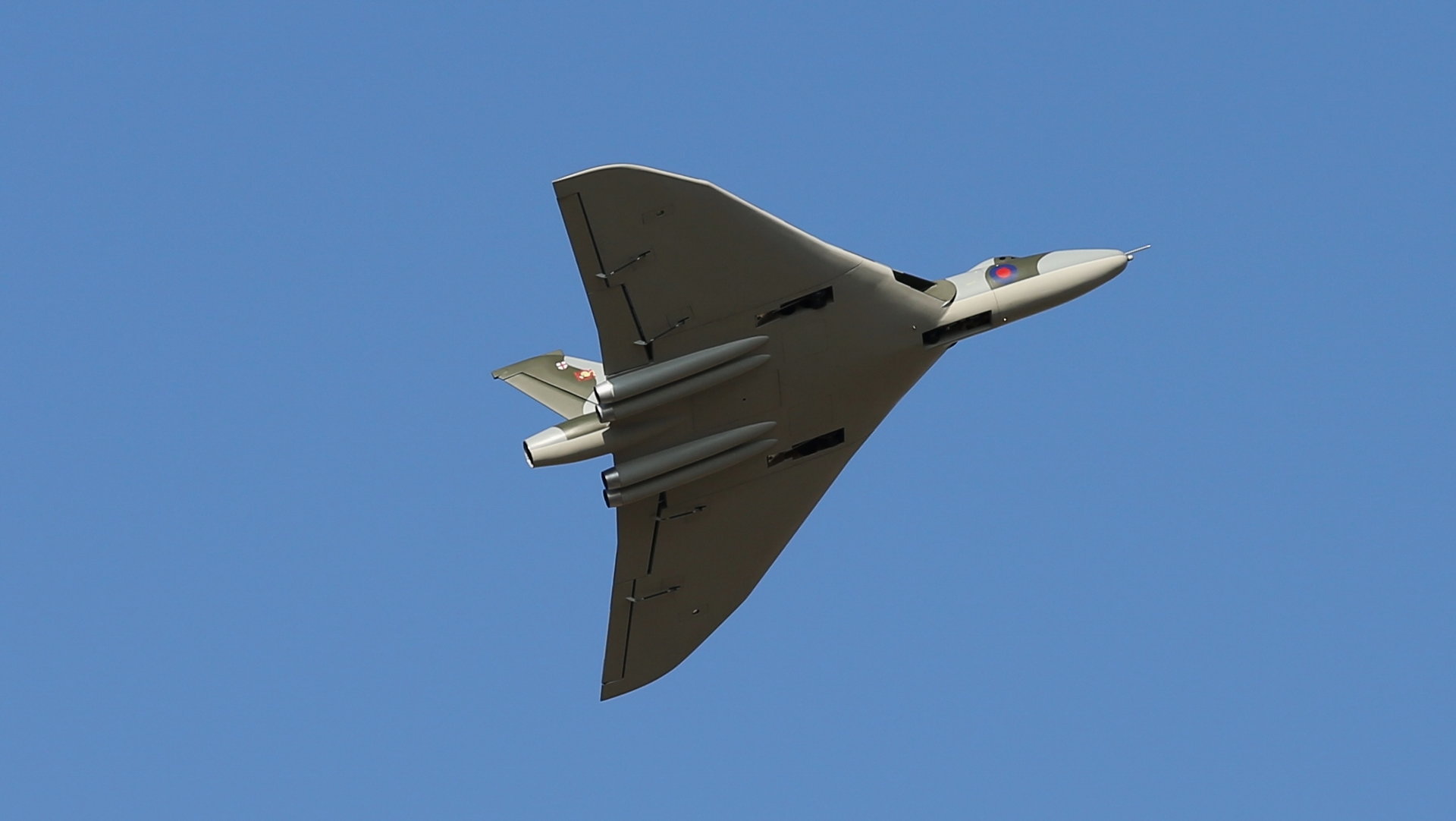
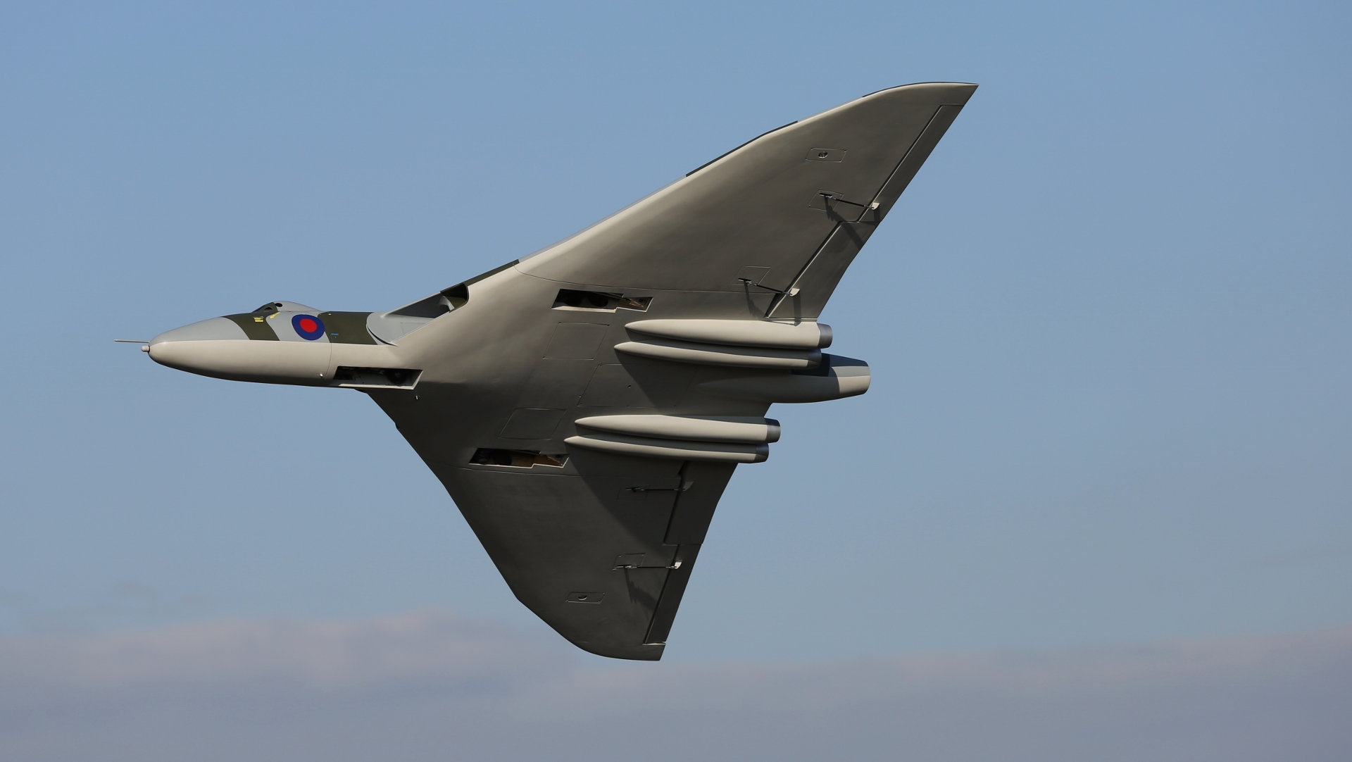
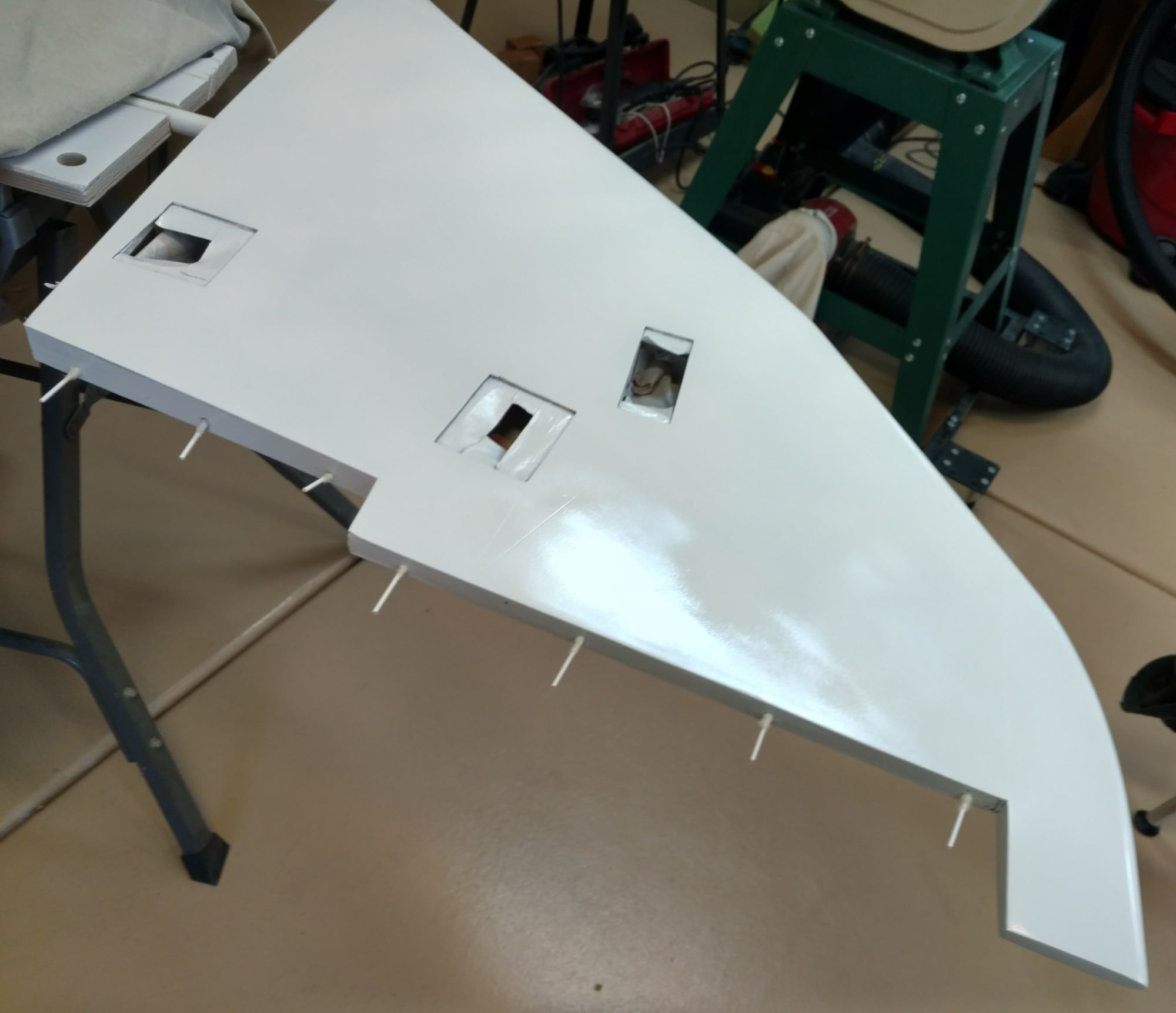
The upper engine nacelles were the supplied vac form ones with the flange removed. internal balsa formers were added to strengthen the thin moulding.
The lower nacelles were made in glass fibre from a mould made by and lent to me by John R. We live quite close in England. These had thick balsa formers added not only for strength but to give more surface area to glue them on with. the edge of the nacelle was thickened all the way round with balsa on the inside to support the thin edge.
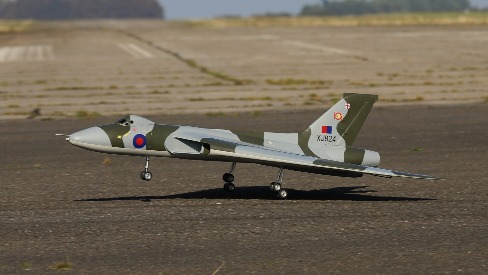
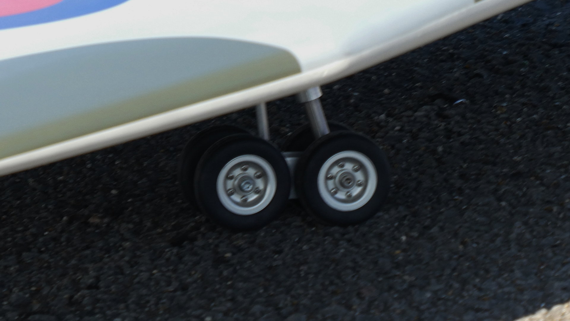
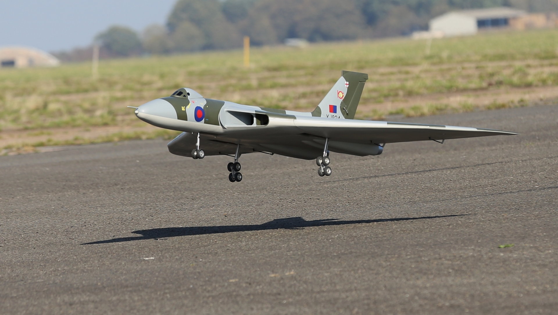
I did not use the TN electric retracts, going for Jet1A mains and a Behotec nose unit with Behotec legs all round.
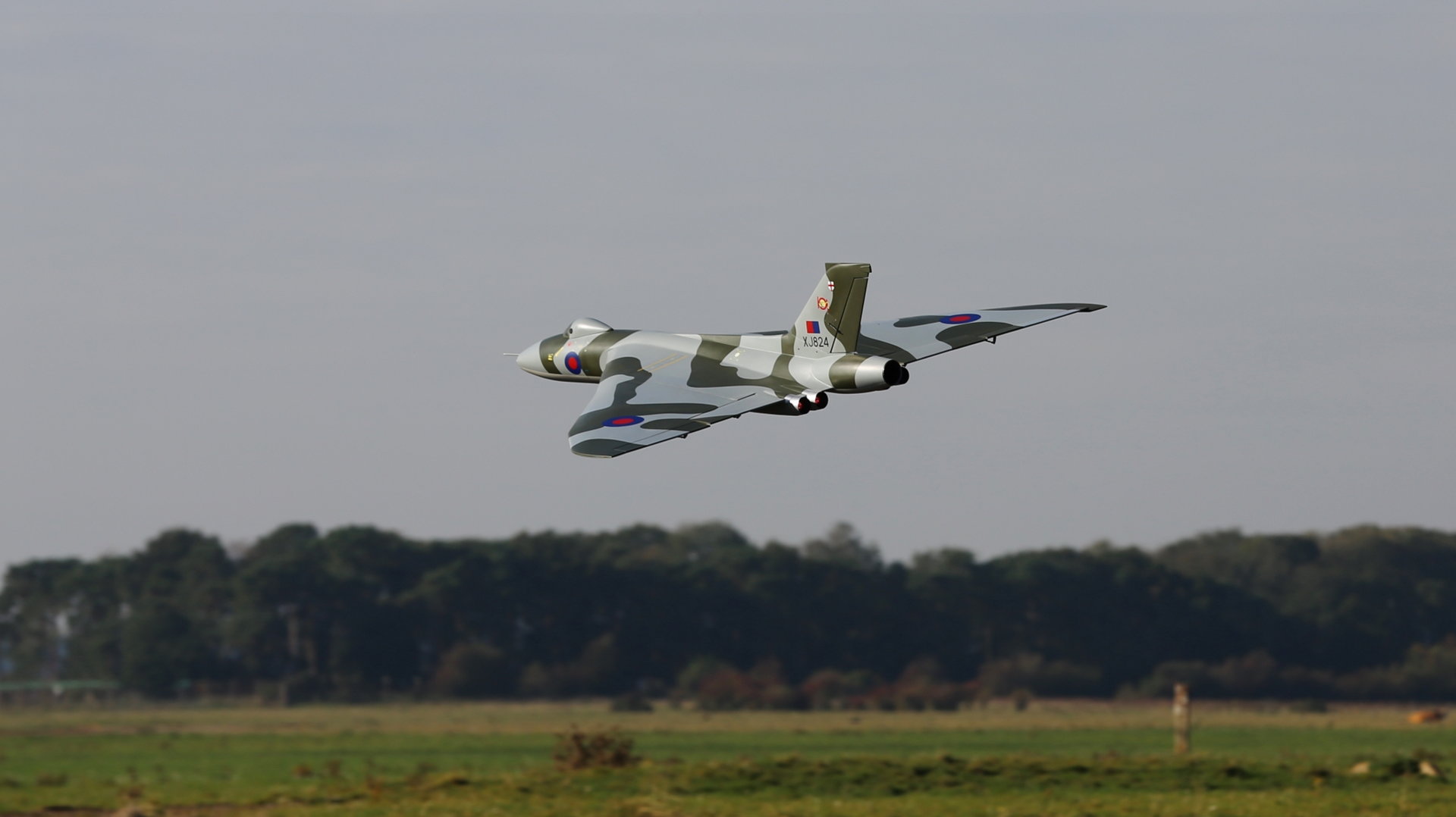
Many thanks to Dave Wilshire for the test flight and I flew it afterwards with a big smile on my face! I have a Powerbox igyro3 fitted now and am working on the gear doors.
Regards
Dave
i would recommend cutting the nose off (if you are going to) before glassing as it will undoubtably cause damage and be harder to make good.
The upper engine nacelles were the supplied vac form ones with the flange removed. internal balsa formers were added to strengthen the thin moulding.
The lower nacelles were made in glass fibre from a mould made by and lent to me by John R. We live quite close in England. These had thick balsa formers added not only for strength but to give more surface area to glue them on with. the edge of the nacelle was thickened all the way round with balsa on the inside to support the thin edge.
I did not use the TN electric retracts, going for Jet1A mains and a Behotec nose unit with Behotec legs all round.
Many thanks to Dave Wilshire for the test flight and I flew it afterwards with a big smile on my face! I have a Powerbox igyro3 fitted now and am working on the gear doors.
Regards
Dave