


Balsa USA Smoothie XL Build
 12-29-2016, 09:48 AM
#26

My Feedback: (427)
golf4two,
Here is my rudder horn installation. Elevator and rudder servos instal
 led
led
Here is my rudder horn installation. Elevator and rudder servos instal
Pappy35 and Check6:
would like to know how you rigged up your rudder control rods/horns. Seems like the broad fuse tail prevents getting the horn attach at or near the hinge line. My plan at the moment is to cut a hole in the tail block. Was hoping one of you has a better idea.
would like to know how you rigged up your rudder control rods/horns. Seems like the broad fuse tail prevents getting the horn attach at or near the hinge line. My plan at the moment is to cut a hole in the tail block. Was hoping one of you has a better idea.


 01-02-2017, 09:43 AM
#28
My Feedback: (427)
Hi Greg,
I made a switch box on the left side of the fuse. Holds the radio and engine switch and the fuel dot. Here are some pics
I made a switch box on the left side of the fuse. Holds the radio and engine switch and the fuel dot. Here are some pics
Pappy and Check6 - I was wondering if you could provide detail on how you're going to mount your on/off switches. Will they be exposed on the side of the fuse? Will you put them under the hatch? Something else?
I just started building mine. The first wing panel will be finished today. Appreciate seeing your progress and ideas!
Greg
I just started building mine. The first wing panel will be finished today. Appreciate seeing your progress and ideas!
Greg
01-03-2017, 05:06 PM
#32
Thread Starter
Join Date: Oct 2006
Location: Collierville, TN
Posts: 602
Likes: 0
Received 0 Likes
on
0 Posts
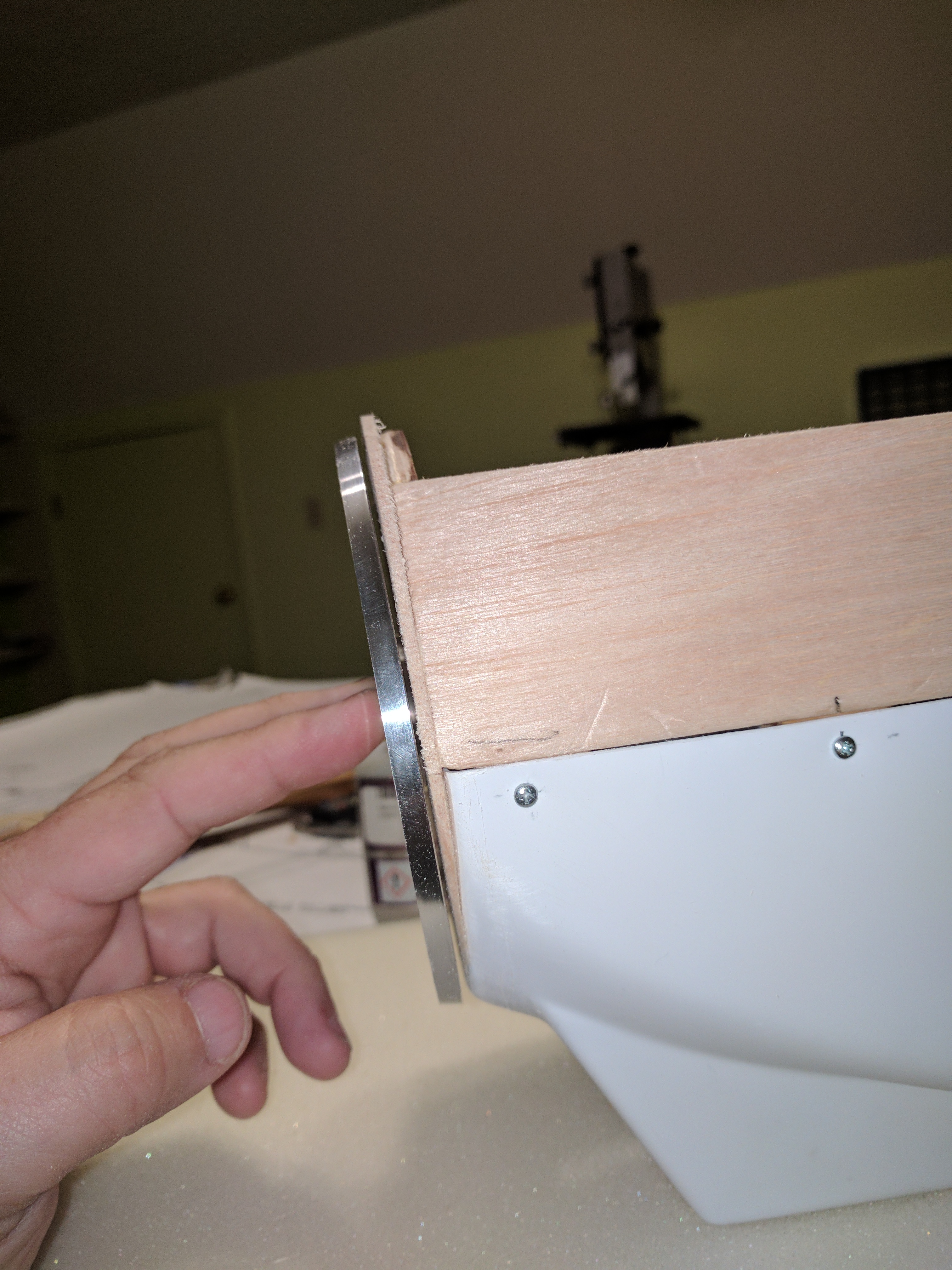
FINALLY got the cowl mounted! Using a term my wife introduced me to, I "borrowed a lot of trouble" by incorporating right/down thrust into a kit that didn't have this designed in. First there was the issue of aligning and securing the firewall at the correct angle. Then finding the location (offset) for the mount holes ensure the spinner lines up. Finally, fiddling with the cowl ring (which is molded for 0-0 angle) to ensure a nice, tight, even gap all around. I'm fussy about some things and a tight spinner gap is a peeve (much to my own detriment) of mine.
Pic 1: Overall view of the installed cowling.
Pic 2, 3 and 4: The tapered cowl ring, spinner gap, sanding block with 120-grit paper. I will be applying filler (finishing resin and microballons as required) to seal the balsa. I probably should have used plywood but that would have been a lot harder to sand and we'll see how this comes out after I prime the cowling. I'll probably open the gap up just a bit more as it's a little too tight like it is but that'll work itself out when I get closer to prepping for finish application (either Solartex or Monokote).
Pic 5: This is one of the few places I've found an error in the instructions. The pictures in the manual came from a Facebook build (or at least I'm pretty sure they did) where the builder was using a large Saito 4-stroke and had to modify the cowling to accommodate the much taller engine. The instructions show how to add balsa extensions to carry this scoop aft to just forward of the front landing gear mount. I found that using the stock cowling and building the extension as shown would have closed off the exit area so I opted to leave it off altogether. As you can see there would have been a much smaller exit area and, to me, this is an unneeded feature that is just dying to get broken off at some point. The appearance of the area is fine just like it is so, well, that's it then. 8-)
01-06-2017, 05:28 PM
#33
Thread Starter
Join Date: Oct 2006
Location: Collierville, TN
Posts: 602
Likes: 0
Received 0 Likes
on
0 Posts
Pretty productive couple of evenings.
Sealed, filled, and sanded the cowl spinner ring (I'll post a picture of that later). I jumped around the manual a bit and started the hatch framing, servo mounts and pushrod guides.
I found two fairly glaring problems with two of the hatch formers (F2A and F3A) and something on the print.
Pic 1: The pen is pointing to what looks like a former doubler. This part isn't in the kit and isn't mentioned in the manual anywhere. I'm not worried about it as the area seems strong enough without it.
Pics 1, 2, 3: Thom25 over on RCGroups forwarded a list of issues he found and, sure enough, this was on there. I posted the list in Check6's thread I believe. It's not totally current as some of the step/pages numbers don't match anything in the manual but this was in there. The formers as supplied were each exactly 1/8" shorter than they needed to be to ensure a smooth upper curve for the hatch sheeting. I opted to cut new ones from scrap wood in the kit rather than trying to fix these. Not really a problem but would have more of a pain had I not known to look.
Pic 4: I also started making the fuselage servo mount and again made use of scrap ply from the kit. I don't yet know exactly where I'm going to put the servos or if the three tail servos (elevator pair and rudder) will be in the same place as this is something I usually wait to do until I have some idea where the CG is going to be. I am using those black Sullivan rigid pushrods for the elevators and used scrap ply knockouts from the plywood wing ribs which will be glued each of the aft fuselage formers as guides. Those pushrods are stiff, but that stiff that they don't need supports.
01-06-2017, 06:36 PM
#34
My Feedback: (427)
Hi Pappy35,
Your right about the hatch formers. I never measured mine and when the hatch was done it had somewhat of a flat spot in the middle. If you notice on my build I added spackle to fair the area in better. You did it the right way. I didn't catch it. Does this make me a bad builder???? LOL . That's why they put erasers on pencils, to correct the mistakes. Your build is looking great and you did an awesome job fitting the engine. I'm just waiting for the weather to break for painting. We are expecting a Nor Easter to hit us tomorrow up to a foot of snow. It's a good thing I have a new snowblower.
Thanks,
Fred
01-06-2017, 08:20 PM
#35
Thread Starter
Join Date: Oct 2006
Location: Collierville, TN
Posts: 602
Likes: 0
Received 0 Likes
on
0 Posts
Thanks Check6.
Haha. Yeah. Spackle makes a great eraser. I'm down to 15 parts left.
I'm from NYC and lived just outside Hartford, CT for 15 years (Pratt & Whitney engineer). I've flown a Piper into Providence a bunch of times and flew over the reservoir every time. That's a nice area and I know what you mean about snow. That's what's nice down here. We just got 3" and that'll be about it for our season. It gets cold here in the Memphis area but not cold enough for long enough to make a mess of things. Hell, I don't even own a snow shovel anymore.
01-06-2017, 09:23 PM
#36
My Feedback: (427)
Hi Pappy35,
The main reservoir is two miles from my house. Funny part is we don't have access to the water . We all have wells and septic systems in N. Scituate and all the other main cities have city water and sewers.Go figure. Any way keep up the great work and postings. I will be going back to my roots. I will be finishing up a Ziroli 96 in. Hellcat.
Thanks,
Fred
01-29-2017, 07:35 PM
#37
Pappy35 and Check6: Miss your posts. Have about run out of wood to glue and was wondering about your electronics placement, covering, estimated initial control throws, etc. This being my first "gasser" I'm floundering a bit. Please continue.....
01-30-2017, 07:31 AM
#39
Thread Starter
Join Date: Oct 2006
Location: Collierville, TN
Posts: 602
Likes: 0
Received 0 Likes
on
0 Posts
I have run into a stone wall making, of all things, the hatch. Made two of them so far and each has come out shaped like a banana. Seemed simple but obviously I don't have the skill needed to sheet compound curves. I soaked the sheeting, set them overnight to dry, glued them the next day, etc. All to no avail. I got frustrated and am taking a short break. Might try planking hatch.V3
I believe I posted the control throws I got from Chad in this thread or Check6's.
I believe I posted the control throws I got from Chad in this thread or Check6's.
01-30-2017, 03:16 PM
#40
I have run into a stone wall making, of all things, the hatch. Made two of them so far and each has come out shaped like a banana. Seemed simple but obviously I don't have the skill needed to sheet compound curves. I soaked the sheeting, set them overnight to dry, glued them the next day, etc. All to no avail. I got frustrated and am taking a short break. Might try planking hatch.V3
I believe I posted the control throws I got from Chad in this thread or Check6's.
I believe I posted the control throws I got from Chad in this thread or Check6's.
Thanks for the tip on the control throws. Still muddling thru on the electronics placement. Maybe a trial balance will help. Got an on-board kill switch and tach and planning on placing them at the top of the headrest.
Don't have much of a painting facility or equipment so going to try 21st Century fabric covering....another new experience! (We fly off of a (not always well maintained) grass strip so need something a bit more durable than standard film covering.
Again, thanks for the responses.
G42
02-03-2017, 12:17 PM
#41
Thread Starter
Join Date: Oct 2006
Location: Collierville, TN
Posts: 602
Likes: 0
Received 0 Likes
on
0 Posts
As I mentioned, this hatch has been giving me fits. I've built two of them now and each ended up bent (not twisted) upwards by about 1/4". That's enough that when the screws are tightened down the hatch would bow in the center leaving a noticeable gap between it and the fuselage top. This occurs due to the structure stress-relieving itself from the compound curve the sheeting needs to take up (yes, I wet the sheeting, formed it to the hatch, and let it dry overnight before gluing, all to no avail).
I'm too picky for that so I redesigned it somewhat to add a shear web down the center (making it like an I-Beam. For this hatch, I selected lower density balsa sticks for the stringers and widened them to 1/4" to provide more gluing area. This will help make the curved sheeting edges a little less critical; the original sticks are very narrow so cutting that curve was a pretty high-tolerance exercise.
Finally, since the stringers are a little heftier, I decided to reduce the sheeting thickness to 1/16". The original sheeting is 3/32" which really doesn't like to form over that curve. I adjusted all the part dimensions to account for the thinner sheeting.
Photos 1, 2 and 3: For the second rebuild I bought new parts from BUSA. For this one I cut the parts from scratch and left a spine down the center of the hatch crutch for the shear webs to glue to. It's not an I-Beam without tensile load bearing sections capping the shear web (structural engineering 101). My intention here is to add structure to resist the sheeting and stringers tendency to want to bend back against the compound curve.
Photos 4 and 5: Started assembling HatchV.3. So far it's straight as an arrow. I'll start the sheeting tonight.
Last edited by pappy35; 02-03-2017 at 12:33 PM.
02-03-2017, 12:49 PM
#42
My Feedback: (427)
Hi Pappy 35,
Looks great!! Mine also had a slight bend when I was finished. I mixed up some epoxy and micro balloons and spread it on the fuse top. Placed a piece of waxed paper on the fused and bolted down the hatch. When dry, I popped the hatch off and sanded the excess filler . This blended everything together.
Looks great!! Mine also had a slight bend when I was finished. I mixed up some epoxy and micro balloons and spread it on the fuse top. Placed a piece of waxed paper on the fused and bolted down the hatch. When dry, I popped the hatch off and sanded the excess filler . This blended everything together.
02-03-2017, 01:16 PM
#43
Thread Starter
Join Date: Oct 2006
Location: Collierville, TN
Posts: 602
Likes: 0
Received 0 Likes
on
0 Posts
Hi Pappy 35,
Looks great!! Mine also had a slight bend when I was finished. I mixed up some epoxy and micro balloons and spread it on the fuse top. Placed a piece of waxed paper on the fused and bolted down the hatch. When dry, I popped the hatch off and sanded the excess filler . This blended everything together.
Looks great!! Mine also had a slight bend when I was finished. I mixed up some epoxy and micro balloons and spread it on the fuse top. Placed a piece of waxed paper on the fused and bolted down the hatch. When dry, I popped the hatch off and sanded the excess filler . This blended everything together.
02-06-2017, 08:15 PM
#44
Thread Starter
Join Date: Oct 2006
Location: Collierville, TN
Posts: 602
Likes: 0
Received 0 Likes
on
0 Posts
Well, HatchV.3 is coming along nicely. Got the top two sheets installed.
Pic 1: I bolted the hatch down to the frame (with a wax paper barrier of course) and then thoroughly wet the sheets, pinned them down, and left them to soak overnight. Next night I applied the glue to the frame, wet just the outside of the sheets, and pinned them down. Next morning, I unbolted the hatch and it stayed flat as a board! Woot!
Pic 2, 3, and 4: I fit the outboard sheets, wet them on the outside, and used masking tape to form them to the curve. I also clamped the hatch down on the corner of the bench to give the sheet overhang someplace to go. Since the plywood frame is hard to pin to, what I've done is only glue the sheet to the stringer. After it dries, I'll use CA to glue it to the frame and them trim it to shape. Repeat for the other side.
Once this is all done, and hopefully unbowed, I'll install the aft canopy frame and the sheeting at the bottom of the canopy.
02-13-2017, 10:35 AM
#46
Thread Starter
Join Date: Oct 2006
Location: Collierville, TN
Posts: 602
Likes: 0
Received 0 Likes
on
0 Posts
On to radio installation infrastructure (I so rarely get to use that word in a sentence...haha).
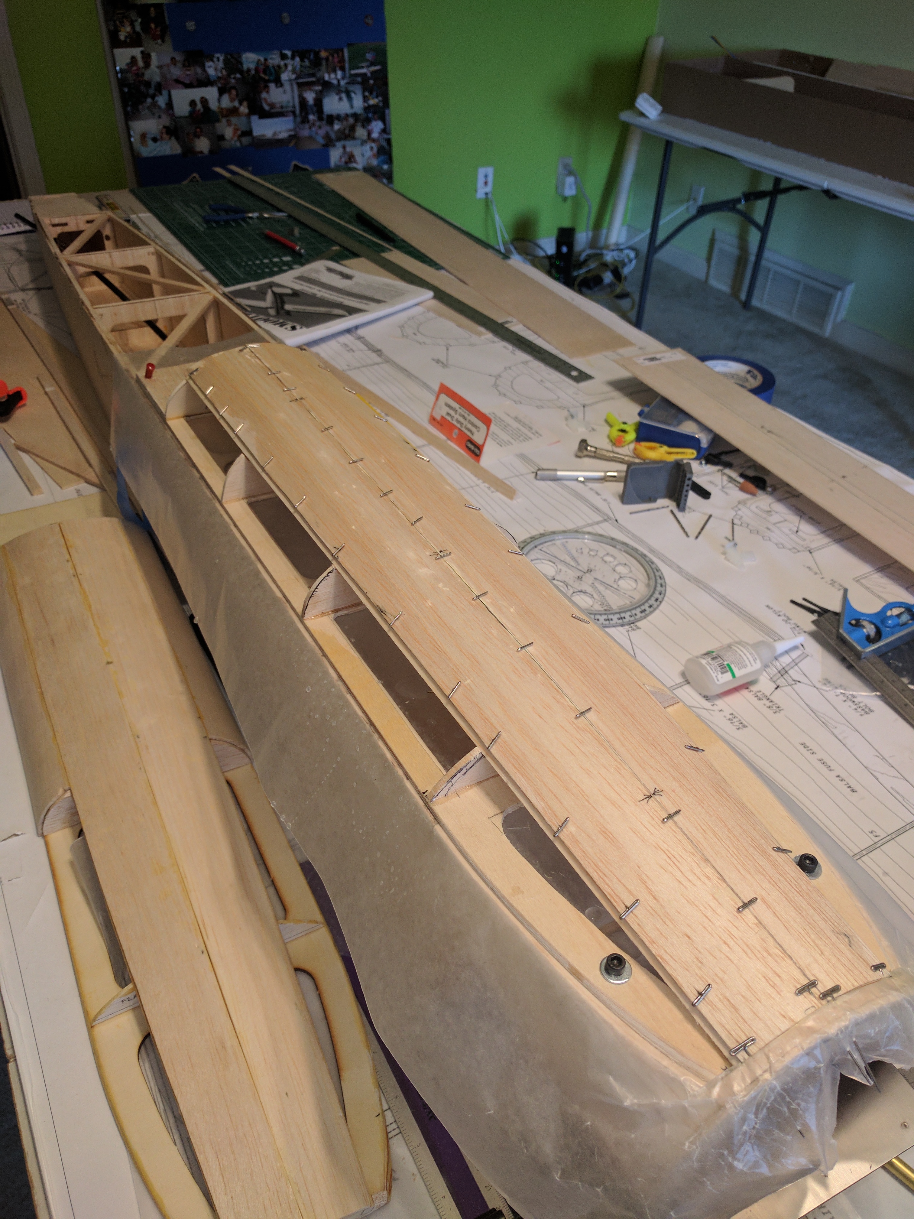
Pic 1 through 6: I used spruce rails and cut plywood reinforcements to place the two elevator and rudder servos. One of the nice things about this kit is that there are quite a lot of 1/8" lite-ply scraps available. I made the rail mounts from one of the hatch or fuselage crutch cut outs and the push rod mounts from plywood rib hole knockouts.
Pic 7: I used a sharpened brass rod to cut the pushrod exit holes. In this picture you can also see how I tapered the tail. It'll be interesting to see how Chad (the kit's designer who is hosting a Facebook video tutorial on building a Smoothie XL) handles this. Even with this much taper I'll have to make fairly large cutouts to provide enough clearance for the rudder pull-pull hardware.
Pic 8: I installed the engine (to center the spinner backplate) so that I could get a jump on shaping the LE. Threw the Fourtitude 12oz. tank in there just to see how it fits. There's plenty of room for a larger tank. Over the weekend someone commented that "everyone hates blocks [of balsa]". I for one would have preferred blocks to form the shape of the forward part of the hatch.
I'm putting off installing the turtle-deck formers until I get most of the heavy sanding out of the way. Most of that is going to be around the hatch and I'm afraid I might break one or more of the stringers what with all the handling needed. Also, I want to wait until I get my pull-pull hardware in so I can get that mocked-up. Once the turtledeck goes on it'll be a lot harder to access that part of the fuselage. I'll rough-fit the wing on somewhere in there also.
Getting a lot closer to looking like an airplane. Woot!
Last edited by pappy35; 02-13-2017 at 11:02 AM.
02-17-2017, 04:40 PM
#47
Thread Starter
Join Date: Oct 2006
Location: Collierville, TN
Posts: 602
Likes: 0
Received 0 Likes
on
0 Posts
Making more progress. Slow and steady wins the race.
Pic 1: Added some filler to smooth out the hatch.
Pic 2, 3, and 4: The slot in the wing crutch front former (I forget the number) is, as indicated in the instructions, a bit shallow and needed to be lengthened in order for the wing to seat properly. I don't have a rasp to this properly so I did the inverse, I cut down the mount tab. For me 26mm was perfect, which amounted to taking off 3-4mm. Once I got that squared away I got the bolt holes drilled and drilled and tapped the wing mount plate. I'm not too sure I want to rely on threads in plywood, even if hardened with thin CA, so I may use brass threaded inserts. I've got a ways to go before I need to make that decision though. The slot is about 1/32" wider than the mount tab, again as mentioned in the instructions, so I added a piece of 1/64" ply to the outside face of each tab to make the wing fit snug.
Pic 5: Starting to look like an airplane. I checked the stab/wing alignment and was very happy to find that it's dead-nuts perfect! Woot!
I'll be doing the rudder pull-pull hardware installation next so that I can get the rear fuselage formers and stringers installed. Getting close to getting ready for finish.
02-20-2017, 01:09 PM
#48
Thread Starter
Join Date: Oct 2006
Location: Collierville, TN
Posts: 602
Likes: 0
Received 0 Likes
on
0 Posts
Got my rudder hardware in so I measured and cut the pull-pull cable clearance holes. Started the overall rough sanding and filling last night too. Making a lot of dust...


02-21-2017, 06:57 PM
#49
Thread Starter
Join Date: Oct 2006
Location: Collierville, TN
Posts: 602
Likes: 0
Received 0 Likes
on
0 Posts
My Dave Brown spinner adapter came in today and it works perfectly. Basically it's a 5mmx0.8mm stud that threads into a long hex shaft. The opposite end is threaded to accept a 10-32 bolt. This bolt is not provided and so you will need to get one that's 1 1/2" long.


02-27-2017, 11:00 AM
#50
Thread Starter
Join Date: Oct 2006
Location: Collierville, TN
Posts: 602
Likes: 0
Received 0 Likes
on
0 Posts
Made quite a bit of progress over the last week.
The last major addition to the wings were the servo mounts. Pretty straight-forward installation starting with the mount rails. These need to be carefully aligned so that the surface filler parts will align with the outer airfoil profile while not requiring too much sanding. Once they were all installed, I added reinforcement plates to the aft rails.


The last major addition to the wings were the servo mounts. Pretty straight-forward installation starting with the mount rails. These need to be carefully aligned so that the surface filler parts will align with the outer airfoil profile while not requiring too much sanding. Once they were all installed, I added reinforcement plates to the aft rails.

