Community
Search
Notices
Electric Pattern Aircraft Discuss epowered pattern aircraft in this forum

Divergent kits

Thread Tools
 
Search this Thread
 
Old 11-06-2019, 06:52 AM
  #26  
jetmech43
My Feedback: (9)
 
Join Date: Oct 2003
Location: Ocala, FL
Posts: 1,723
Likes: 0
Received 5 Likes on 5 Posts
Default

Originally Posted by speedracerntrixie
In the Pattern forum look for the thread " Pattern Biplane".
Ok thanks
Old 11-06-2019, 08:58 AM
  #27  
speedracerntrixie
Thread Starter
My Feedback: (29)
 
speedracerntrixie's Avatar
 
Join Date: Jun 2010
Location: Happy Valley, Oregon
Posts: 9,515
Received 176 Likes on 151 Posts
Default


Time to apply PVA to the fuselage mold. I have had mixed results spraying PVA so I apply with a foam brush.


PVA has been applied, I will be able to spray primer into the mold after about an hour of dry time.
Old 11-06-2019, 12:51 PM
  #28  
speedracerntrixie
Thread Starter
My Feedback: (29)
 
speedracerntrixie's Avatar
 
Join Date: Jun 2010
Location: Happy Valley, Oregon
Posts: 9,515
Received 176 Likes on 151 Posts
Default


A light coat of Klass Kote primer applied.


First layer of surface cloth in the mold.
Old 11-06-2019, 12:54 PM
  #29  
speedracerntrixie
Thread Starter
My Feedback: (29)
 
speedracerntrixie's Avatar
 
Join Date: Jun 2010
Location: Happy Valley, Oregon
Posts: 9,515
Received 176 Likes on 151 Posts
Default


Balsa core, CF re enforcements and inner glass skin applied


Peel ply, barrier film and breather in the mold.
Old 11-06-2019, 12:57 PM
  #30  
speedracerntrixie
Thread Starter
My Feedback: (29)
 
speedracerntrixie's Avatar
 
Join Date: Jun 2010
Location: Happy Valley, Oregon
Posts: 9,515
Received 176 Likes on 151 Posts
Default


In the bag and under vacuum.
Old 11-06-2019, 02:45 PM
  #31  
flywilly
My Feedback: (121)
 
Join Date: Feb 2002
Location: glen allen, VA,
Posts: 2,264
Likes: 0
Received 30 Likes on 29 Posts
Default

Very impressive, Shawn.
Old 11-06-2019, 03:04 PM
  #32  
drac1
My Feedback: (4)
 
drac1's Avatar
 
Join Date: Jul 2008
Location: Romaine, Tasmania, AUSTRALIA
Posts: 1,737
Received 7 Likes on 7 Posts
Default

Sure is impressive.

It's great to see how it's done. I doubt it's as easy as Shawn makes it look though
I hope to be having a go soon, so I'm watching very keenly
Old 11-07-2019, 09:02 AM
  #33  
speedracerntrixie
Thread Starter
My Feedback: (29)
 
speedracerntrixie's Avatar
 
Join Date: Jun 2010
Location: Happy Valley, Oregon
Posts: 9,515
Received 176 Likes on 151 Posts
Default

Today is pretty much a repeat of yesterday so I'm not going to back through the steps. Once the second fuselage half is done and I have the shells joined the build part of the thread will begin. It actually starts with sheeting the bottom wing. Once the bottom wing is built it gets mounter to the fuselage and used as a baseline to get the upper wing and stab correctly aligned.
Old 11-07-2019, 09:07 AM
  #34  
speedracerntrixie
Thread Starter
My Feedback: (29)
 
speedracerntrixie's Avatar
 
Join Date: Jun 2010
Location: Happy Valley, Oregon
Posts: 9,515
Received 176 Likes on 151 Posts
Default


Results of yesterday out of the bag and has the peel ply removed.
Old 11-09-2019, 12:25 PM
  #35  
speedracerntrixie
Thread Starter
My Feedback: (29)
 
speedracerntrixie's Avatar
 
Join Date: Jun 2010
Location: Happy Valley, Oregon
Posts: 9,515
Received 176 Likes on 151 Posts
Default


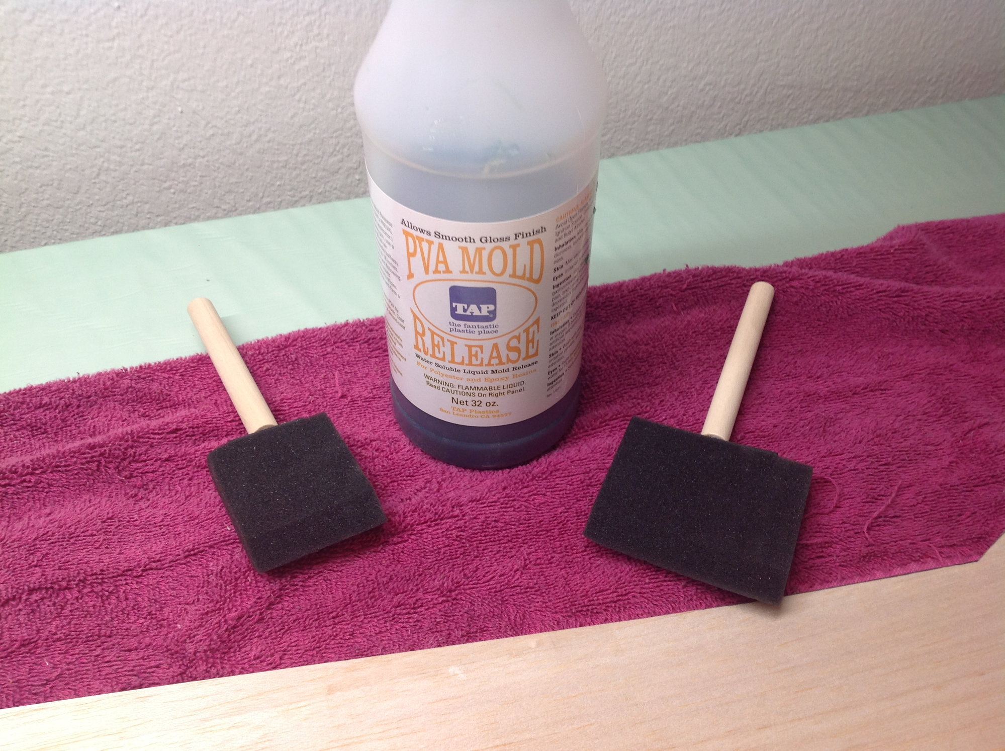
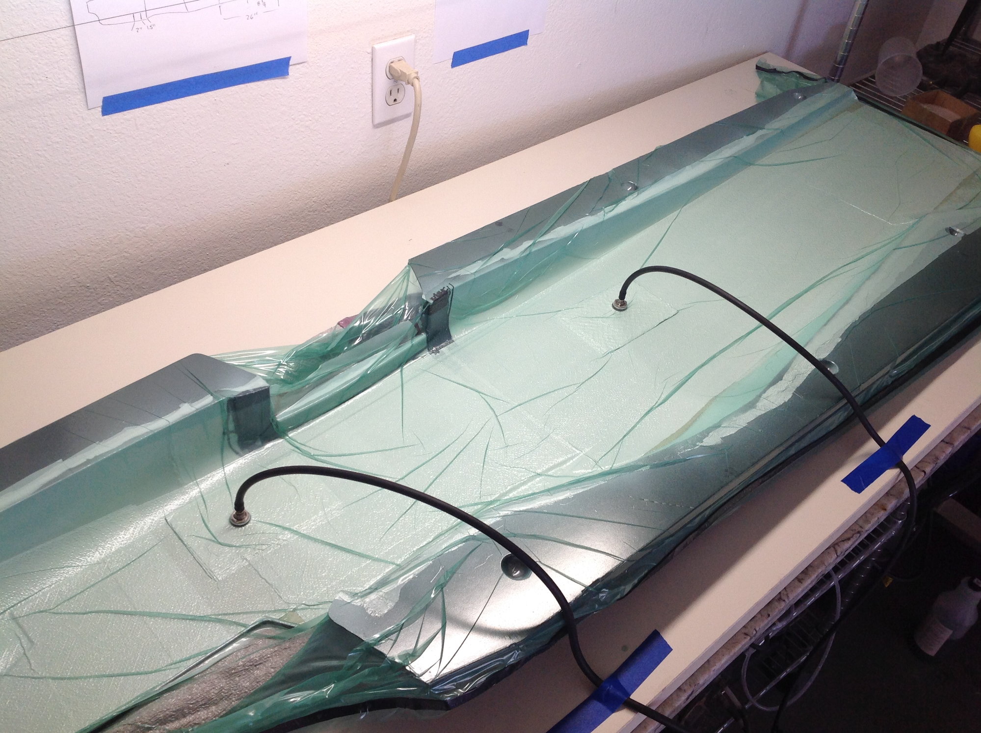
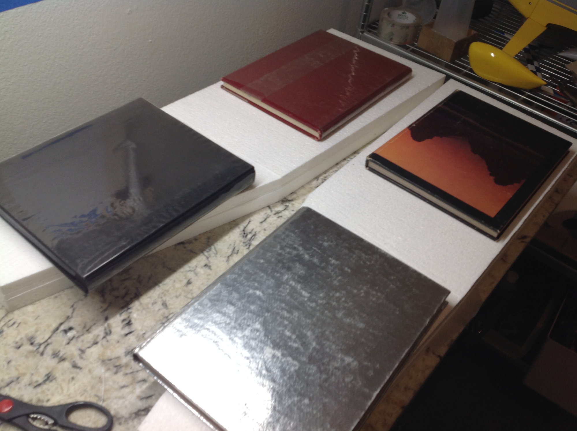
Now that the second fuselage shell is done it is now time to glue all the formers and stab support in place. In order to do that I needed to make up the material that those parts are cut from. Fairly simple, I take 1/8" structural foam and vacuum bag fiberglass and carbon fiber skins to the foam. The parts are cut out on a Dremel scroll saw.
Old 11-09-2019, 12:29 PM
  #36  
speedracerntrixie
Thread Starter
My Feedback: (29)
 
speedracerntrixie's Avatar
 
Join Date: Jun 2010
Location: Happy Valley, Oregon
Posts: 9,515
Received 176 Likes on 151 Posts
Default


Now that my workbench is not occupied with the fuselage molds I can get started on the wings and stabs. The first step is to make up some servo boxes.
Old 11-13-2019, 08:00 AM
  #37  
GootyS
 
Join Date: Mar 2009
Location: Milton Keynes, UK
Posts: 14
Likes: 0
Received 0 Likes on 0 Posts
Default

What % foil thickness is being used on Bipes? I have seen some that look super thin.
Old 11-14-2019, 12:08 PM
  #38  
speedracerntrixie
Thread Starter
My Feedback: (29)
 
speedracerntrixie's Avatar
 
Join Date: Jun 2010
Location: Happy Valley, Oregon
Posts: 9,515
Received 176 Likes on 151 Posts
Default

I would have to look at my notes but from memory I used 9% at the root, 10% mid span and 12% at the tip.
Old 11-16-2019, 08:31 AM
  #39  
speedracerntrixie
Thread Starter
My Feedback: (29)
 
speedracerntrixie's Avatar
 
Join Date: Jun 2010
Location: Happy Valley, Oregon
Posts: 9,515
Received 176 Likes on 151 Posts
Default

Sorry this has been a bit slow lately. I have the next couple of days free and will be adding updates focusing on the wings and stabs.
Old 11-16-2019, 01:05 PM
  #40  
ted32776
 
Join Date: Jan 2018
Location: Sorrento, Florida
Posts: 135
Likes: 0
Received 11 Likes on 10 Posts
Default

All right, we'll let it go this time, young man, but next time...….it goes on your permanent record.
Old 11-17-2019, 04:14 PM
  #41  
speedracerntrixie
Thread Starter
My Feedback: (29)
 
speedracerntrixie's Avatar
 
Join Date: Jun 2010
Location: Happy Valley, Oregon
Posts: 9,515
Received 176 Likes on 151 Posts
Default


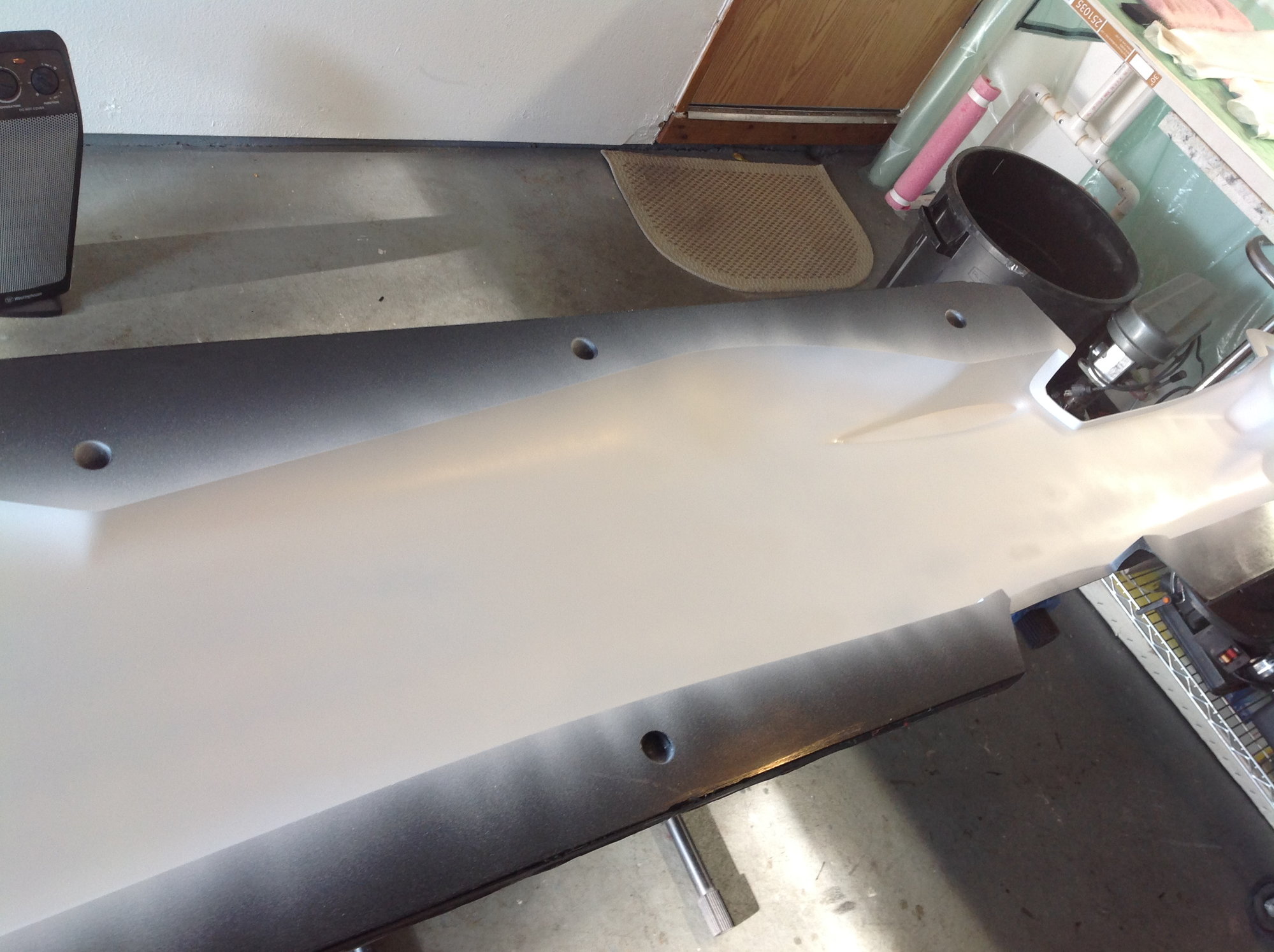
Once the servo boxes are sanded flush I moved onto installing the stab and upper wing tube sleeves. These are installed with the outter tube supports. The cores are then placed back in their shucks with a plastic sheet between the cores and shucks.
Old 11-18-2019, 05:06 AM
  #42  
ted32776
 
Join Date: Jan 2018
Location: Sorrento, Florida
Posts: 135
Likes: 0
Received 11 Likes on 10 Posts
Default

How about some rough dimensions for servo positions and initial control surface cuts after sheeting, material choice [balsa or liteply] for the tube guides formers, preferred method for cutting the longer servo lead holes on the wings [I'm guessing an appropriately sized metal tube with serrations filed in the end will be ok]?
Old 11-18-2019, 10:05 AM
  #43  
GootyS
 
Join Date: Mar 2009
Location: Milton Keynes, UK
Posts: 14
Likes: 0
Received 0 Likes on 0 Posts
Default

Did you buy or make your own wing tubes etc?
Old 11-18-2019, 06:03 PM
  #44  
speedracerntrixie
Thread Starter
My Feedback: (29)
 
speedracerntrixie's Avatar
 
Join Date: Jun 2010
Location: Happy Valley, Oregon
Posts: 9,515
Received 176 Likes on 151 Posts
Default


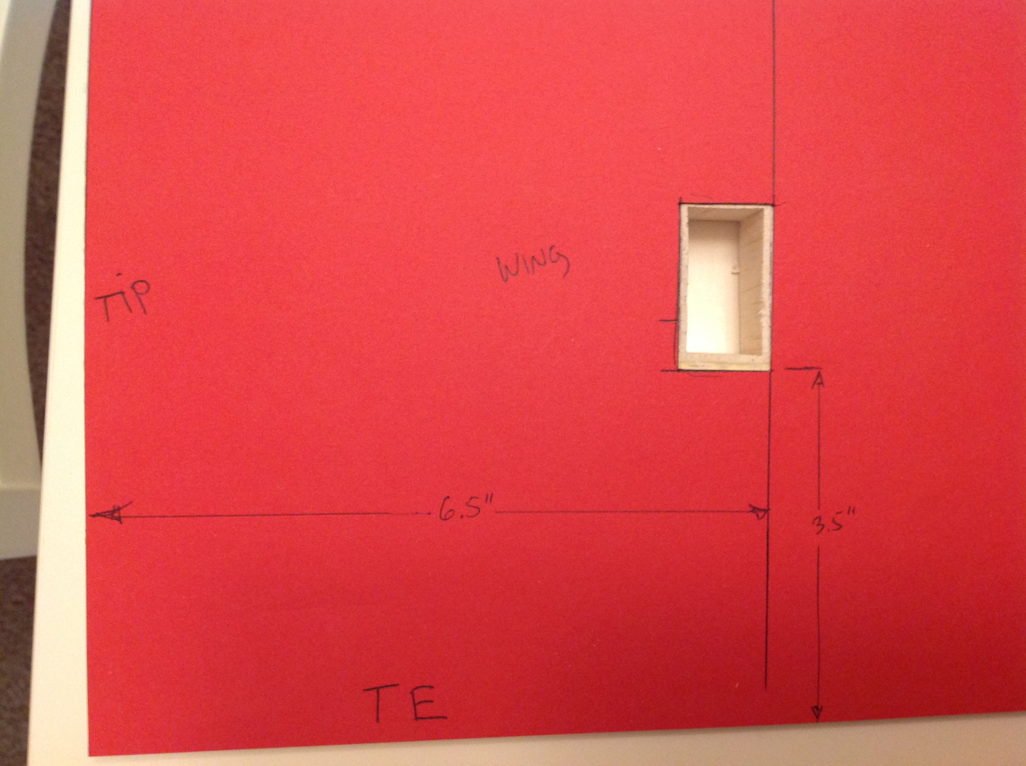
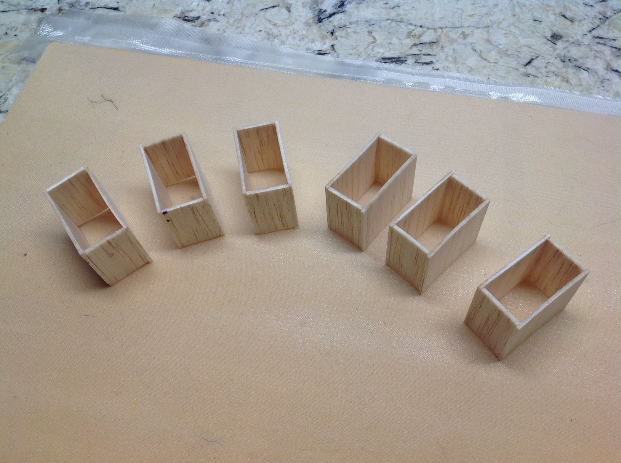
Aileron servo location. Dimensions are taken from the outer tip of the inboard wing cores and trailing edge.


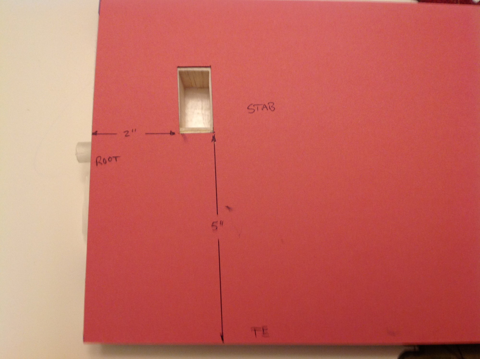
Elevator servo location, dimensions taken from root and trailing edge. The boxes have an ID of 3/4"X1.5". Planned servos are MKS 69HV.
Old 11-18-2019, 06:11 PM
  #45  
speedracerntrixie
Thread Starter
My Feedback: (29)
 
speedracerntrixie's Avatar
 
Join Date: Jun 2010
Location: Happy Valley, Oregon
Posts: 9,515
Received 176 Likes on 151 Posts
Default


Using the a wing fence/strut mount as a template, sand a groove into the 4 outter wing panels.


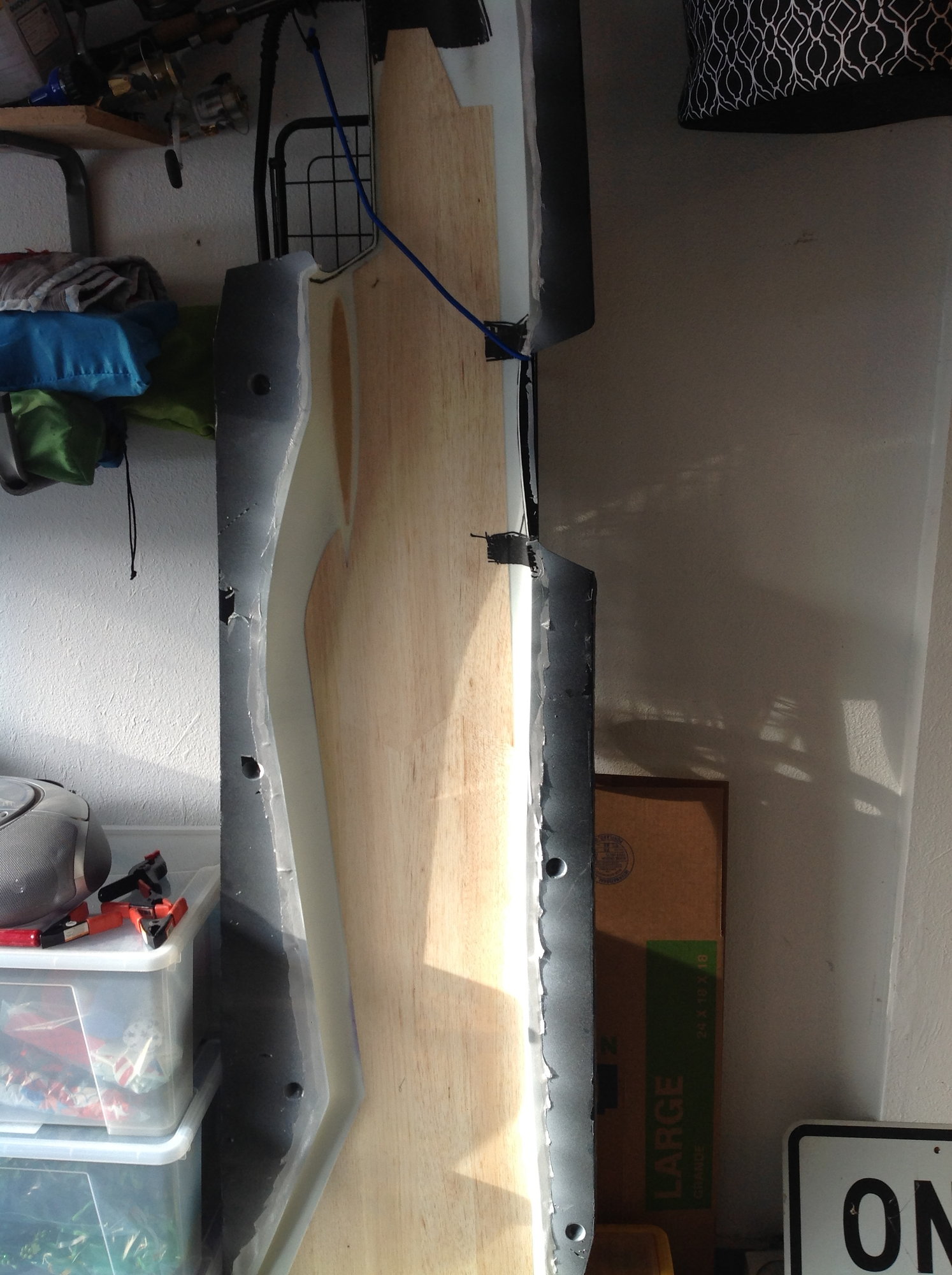
Make a master set of wing shucks. I had to mix and match a few inner and outer shucks until I got a set that matched. Here they have been glued together with Titebond. All wing sheeting will be done using this one pair of shucks.
Old 11-18-2019, 06:16 PM
  #46  
speedracerntrixie
Thread Starter
My Feedback: (29)
 
speedracerntrixie's Avatar
 
Join Date: Jun 2010
Location: Happy Valley, Oregon
Posts: 9,515
Received 176 Likes on 151 Posts
Default


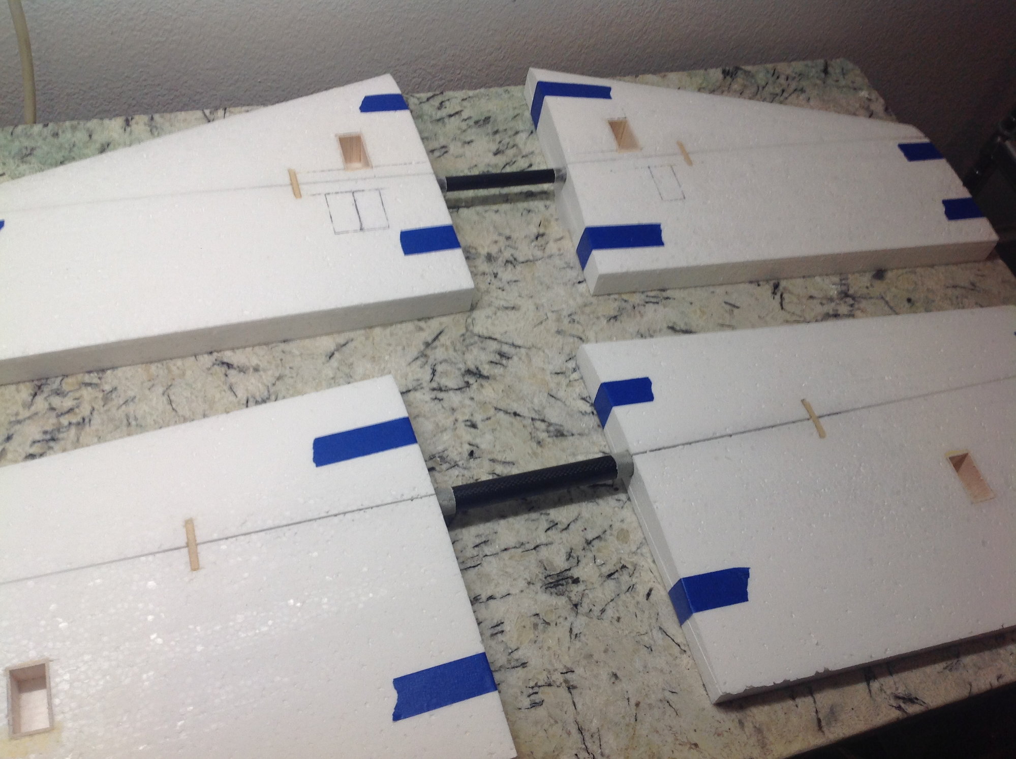
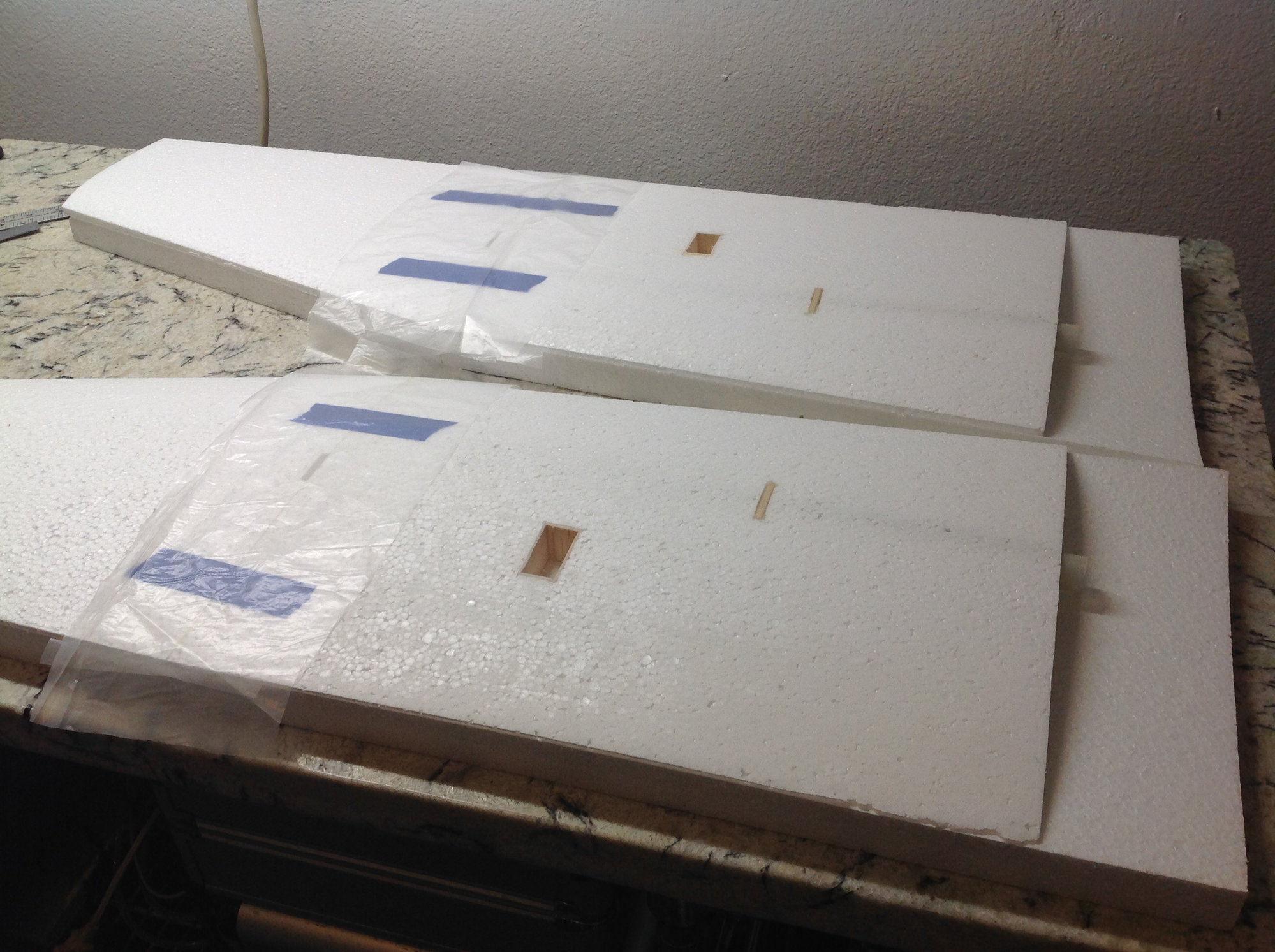
The lower wing cores are then glued together with Titebond. The lower wing gets sheeted first because the shucks will need to have 3.5" cut off the root end to sheet the upper wing.


To keep the cores straight while the glue dries, Top shucks are placed on the core and weighted down.
Old 11-18-2019, 06:20 PM
  #47  
speedracerntrixie
Thread Starter
My Feedback: (29)
 
speedracerntrixie's Avatar
 
Join Date: Jun 2010
Location: Happy Valley, Oregon
Posts: 9,515
Received 176 Likes on 151 Posts
Default

Gooty, I buy the carbon fiber wing and stab tubes but make the sleeves out of fiberglass. I have found that the CF tubes fluxuate in size some so the sleeves are made from the exact tubes that get shipped with each kit. It's the only way to make sure the sleeves fit the tubes well.
Old 11-19-2019, 12:20 AM
  #48  
GootyS
 
Join Date: Mar 2009
Location: Milton Keynes, UK
Posts: 14
Likes: 0
Received 0 Likes on 0 Posts
Default

That makes perfect sense thank you. On with the build :-)
Old 11-19-2019, 05:17 PM
  #49  
speedracerntrixie
Thread Starter
My Feedback: (29)
 
speedracerntrixie's Avatar
 
Join Date: Jun 2010
Location: Happy Valley, Oregon
Posts: 9,515
Received 176 Likes on 151 Posts
Default


Repeat for the upper wing.
Old 11-20-2019, 05:10 PM
  #50  
speedracerntrixie
Thread Starter
My Feedback: (29)
 
speedracerntrixie's Avatar
 
Join Date: Jun 2010
Location: Happy Valley, Oregon
Posts: 9,515
Received 176 Likes on 151 Posts
Default


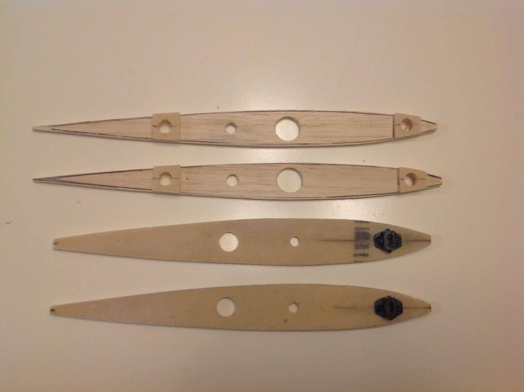
Root ribs for the upper wing panels and stabs were made today. The wing ribs are made out of medium balsa with doublers of fiberglass skinned foam. The stab roots are made from the glass skinned foam. The stab adjusters are held in place with CA and CF pins. The position of the stab adjusters and wing anti rotation pins is not critical, I just like to have them as far away from the wing/stab tubes as possible.


Contact Us - Archive - Advertising - Cookie Policy - Privacy Statement - Terms of Service -

Copyright © 2024 MH Sub I, LLC dba Internet Brands. All rights reserved. Use of this site indicates your consent to the Terms of Use.